Difference between revisions of "Velleman PCSGU250"
Jump to navigation
Jump to search
ChristophF (talk | contribs) |
Uwe Hermann (talk | contribs) (Set status to Planned.) |
||
| (10 intermediate revisions by 3 users not shown) | |||
| Line 1: | Line 1: | ||
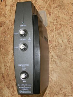
[[File: | [[File:VELLEMANN_PCSGU250_FRONT.jpg|thumb|right|Velleman PCSU250]] | ||
The [http://www.velleman.eu/products/view/?id=377622] is an inexpensive USB-based oscilloscope. It has 2 channels, an analog bandwidth of 12MHz and 25MS/s sampling rate. | The [http://www.velleman.eu/products/view/?id=377622 PCSU250] is an inexpensive USB-based oscilloscope. It has 2 channels, an analog bandwidth of 12MHz and 25MS/s sampling rate. Additionally a signal generator is included. | ||
See [[Velleman PCSU250/Info]] for more details (such as '''lsusb -vvv''' output) about the device. | See [[Velleman PCSU250/Info]] for more details (such as '''lsusb -vvv''' output) about the device. | ||
| Line 13: | Line 13: | ||
'''USB interface''' | '''USB interface''' | ||
* | * Inluded in the PIC. | ||
'''Analog frontend''' | '''Analog frontend''' | ||
| Line 27: | Line 23: | ||
* 3 x [http://www.ti.com/product/tps76601 Texas Instruments TPS766xx] voltage regulators (IC19=1V, IC20=2.5V, IC21=3.3V) | * 3 x [http://www.ti.com/product/tps76601 Texas Instruments TPS766xx] voltage regulators (IC19=1V, IC20=2.5V, IC21=3.3V) | ||
'''Trigger Level''' | |||
* [http://www.nxp.com/documents/data_sheet/74HC_HCT4051_Q100.pdf 74HCT4051D] 8-channel analog multiplexer/demultiplexer with 15 resistors, is that a R2R DAC??? I would guess this one is for the trigger level | |||
'''Signal Generator''' | '''Signal Generator''' | ||
* [http://www.ti.com/product/dac0800 DAC0800LCM] 8-Bit Digital-to-Analog Converter Settling Time 0.1 µs, does that mean max. 10Mhz Sample rate? | * [http://www.ti.com/product/dac0800 DAC0800LCM] 8-Bit Digital-to-Analog Converter Settling Time 0.1 µs, does that mean max. 10Mhz Sample rate? | ||
*[http://www.b-kainka.de/Daten/OPV/tl081crev1.pdf TL081C] JFET OPAMP | |||
*[http://www.b-kainka.de/Daten/OPV/tl081crev1.pdf | * [http://www.ti.com/product/lm6172 lm6172] Dual High Speed, Low Power, Low Distortion Voltage Feedback Amplifiers 100Mhz GBW | ||
* [http://www.ti.com/product/ | |||
== Photos == | == Photos == | ||
<gallery> | <gallery> | ||
File:VELLEMANN_PCSGU250_FRONT.jpg|<small>Device, front</small> | |||
File:PCSGU250_PCB.JPG|<small>PCB, front</small> | File:PCSGU250_PCB.JPG|<small>PCB, front</small> | ||
File:VELLEMANN_PCSGU250_PCB_BACK.jpg|<small>PCB, back</small> | File:VELLEMANN_PCSGU250_PCB_BACK.jpg|<small>PCB, back</small> | ||
File:VELLEMANN_PCSGU250_SIGNAL_GEN.JPG|<small> | File:VELLEMANN_PCSGU250_SIGNAL_GEN.JPG|<small>Signal generator or trigger circuit?</small> | ||
File:VELLEMANN_PCSGU250_OUTPUT_STAGE.jpg|<small> | File:VELLEMANN_PCSGU250_OUTPUT_STAGE.jpg|<small>Output stage</small> | ||
File:VELLEMANN_PCSGU250_RUSTY_METAL.jpg|<small>Chunk of rusty metal for weight</small> | |||
</gallery> | </gallery> | ||
== Protocol == | == Protocol == | ||
* https://bitbucket.org/abbradar/scope/src | |||
* http://forum.velleman.eu/viewtopic.php?f=10&t=3586&start=15 | |||
* https://app.box.com/s/cxybc16r7o5kqb65u6ct | |||
== Resources == | == Resources == | ||
* | * [http://www.velleman.eu/downloads/0/user/usermanual_pclab2000lt.pdf Vendor manual] | ||
* [http://www.velleman.eu/downloads/files/downloads/pclab2000lt_v1_12_setup.zip Vendor software] | |||
* [http://www.velleman.eu/downloads/files/downloads/pcsgu250_dll_rev1.zip Vendor SDK] | |||
* [http://www.velleman.eu/downloads/0/infosheets/pcsgu250_uk.pdf Infosheet] | |||
[[Category:Device]] | [[Category:Device]] | ||
[[Category:Oscilloscope]] | [[Category:Oscilloscope]] | ||
[[Category: | [[Category:Planned]] | ||
Latest revision as of 18:46, 20 December 2016
The PCSU250 is an inexpensive USB-based oscilloscope. It has 2 channels, an analog bandwidth of 12MHz and 25MS/s sampling rate. Additionally a signal generator is included.
See Velleman PCSU250/Info for more details (such as lsusb -vvv output) about the device.
Hardware
Control logic
- Xilinx XC3S50 50K-gate FPGA
- 50MHz crystal: 50.000 Y0KE (clock source for the Xilinx FPGA)
- Microchip PIC18LF2450-I/SP 8-bit microcontroller
USB interface
- Inluded in the PIC.
Analog frontend
- 4 x SIR-S4-105A IZ Goodsky 5V relay (2 per input channel)
- 2 x Texas Instruments OPA2354 op-amps
- 1 x Analog Devices AD9288BST-40 Dual 8-bit 40MSPS A/D converters
Power
- 3 x Texas Instruments TPS766xx voltage regulators (IC19=1V, IC20=2.5V, IC21=3.3V)
Trigger Level
- 74HCT4051D 8-channel analog multiplexer/demultiplexer with 15 resistors, is that a R2R DAC??? I would guess this one is for the trigger level
Signal Generator
- DAC0800LCM 8-Bit Digital-to-Analog Converter Settling Time 0.1 µs, does that mean max. 10Mhz Sample rate?
- TL081C JFET OPAMP
- lm6172 Dual High Speed, Low Power, Low Distortion Voltage Feedback Amplifiers 100Mhz GBW
Photos
Protocol
- https://bitbucket.org/abbradar/scope/src
- http://forum.velleman.eu/viewtopic.php?f=10&t=3586&start=15
- https://app.box.com/s/cxybc16r7o5kqb65u6ct


