User talk:Mrnuke
Focussz Fosc21 Protocol
I'm working on reverse engineering the protocol of the Focussz_Fosc21 basic oscilloscope. The device is an 8-bit microcontroller hooked up to USB-serial chip. the communication is 115200,8n1.
Since the communication is done via USB, Wireshark is the best friend. With a bit of filtering, we can get just the serial communication. Once the bytes are put into packets, a communication session looks like:
Send Packets:
1.  ff 05 7f 7d 06 73
2.  ff 05 7f 7d 06 73
3. blablabla
Get bored, we were sending at the wrong baud anyway
switch baud 115200
Bytenum  0  1  2  3  4  5  6  7  8  9 10 11
OUT ==> ff 05 61 7d 06 73
IN <==  ff 0b 9b e6 80 1a 11 20 64 32 03 04
OUT ==> ff 09 60 64 40 97 64 7d c0 03
OUT ==> ff 09 60 64 40 97 64 7d d1 03
OUT ==> ff 09 60 64 40 97 64 7d 01 03
OUT ==> ff 09 60 64 40 97 64 7d 00 03
IN <==  ff 07 40 36 40 26 ff 03
OUT ==> ff 09 60 64 40 97 64 7d c0 03
IN <==  ff 07 40 36 40 26 ff 03
IN <==  ff 07 40 36 40 26 ff 03
OUT ==> ff 09 60 64 40 97 64 7d c0 03
IN <==  ff 07 40 36 40 26 ff 03
OUT ==> ff 09 60 64 40 97 64 7d c0 03
IN <==  ff 07 40 36 40 26 ff 03
IN <==  ff 07 40 36 40 26 ff 03
IN <==  ff 05 00 12 01 00 32 28 61 01 /* This looks like an actual reading */
IN <==  ff 05 00 02 01 00 1e 79 1e 01 /* This looks like an actual reading */
/*
 * From now on, only the scope is sending packets.
 * All subsequent packets have this format.
 */
ID packet
The first packet exchange seems to be an identification exchange, hence the name "ID packet".
The following is an example of an ID packet exchage:
OUT ==> ff 05 61 7d 06 73
IN <==  ff 0b 9b e6 80 1a 11 20 64 32 03 04
It seems that the first packet sent by the host varies bytes [2] and [3] with each run. So I fed it all possible values to see how the device responds. The trace is here. The ID reply seems to be a naive XOR manipulation of the ID request plus some unidentified bytes. It appears that, for the ID packet:
- OUT[2] = IN[2] xor IN[4] xor 0xfc
- OUT[3] = IN[3] xor IN[5] xor 0xe8
- OUT[4] = IN[2] xor IN[4] xor 0xe7
- OUT[5] = IN[2] xor IN[3] xor IN[5] xor 0x75
A few more captures
Ch1-high Ch2-low
/*
 * Focussz Fosc21 capture
 * Channel 1: +12V 1X, input positive saturation
 * Channel 2: -12V 10X, input negative saturation
 */

/* Just switched to 115200 baud */
OUT ==> ff 05 b9 58 06 73
IN <==  ff 0b 43 c3 58 e7 11 20 64 32 03 04
OUT ==> ff 09 60 64 40 97 64 7d c0 03
OUT ==> ff 09 60 64 40 97 64 7d d1 03
OUT ==> ff 09 60 64 40 97 64 7d 01 03
IN <==  ff 07 40 36 40 26 ff 03
OUT ==> ff 09 60 64 40 97 64 7d 00 03
IN <==  ff 07 40 36 40 26 ff 03
OUT ==> ff 09 60 64 40 97 64 7d c0 03
IN <==  ff 07 40 36 40 26 ff 03
IN <==  ff 07 40 36 40 26 ff 03
OUT ==> ff 09 60 64 40 97 64 7d c0 03
IN <==  ff 07 40 36 40 26 ff 03
IN <==  ff 07 40 36 40 26 ff 03
OUT ==> ff 09 60 64 40 97 64 7d c0 03
IN <==  ff 07 40 36 40 26 ff 03
IN <==  ff 05 00 02 01 00 fe 02 07 02
IN <==  ff 05 00 02 01 00 fe 02 07 02
/* All other IN packets repeat. No more OUT packets */
Ch1-low Ch2-high
/*
 * Focussz Fosc21 capture
 * Channel 1: -12V 10X, input negative saturation
 * Channel 2: +12V 1X, input positive saturation
 */

/* Just switched to 115200 baud */
OUT ==> ff 05 92 45 06 73
IN <==  ff 0b 68 de 73 d1 11 20 64 32 03 04
OUT ==> ff 09 60 64 40 97 64 7d c0 03
OUT ==> ff 09 60 64 40 97 64 7d d1 03
OUT ==> ff 09 60 64 40 97 64 7d 01 03
IN <==  ff 07 40 36 40 26 ff 03
OUT ==> ff 09 60 64 40 97 64 7d 00 03
IN <==  ff 07 40 36 40 26 ff 03
OUT ==> ff 09 60 64 40 97 64 7d c0 03
IN <==  ff 07 40 36 40 26 ff 03
IN <==  ff 07 40 36 40 26 ff 03
OUT ==> ff 09 60 64 40 97 64 7d c0 03
IN <==  ff 07 40 36 40 26 ff 03
IN <==  ff 07 40 36 40 26 ff 03
OUT ==> ff 09 60 64 40 97 64 7d c0 03
IN <==  ff 07 40 36 40 26 ff 03
IN <==  ff 05 00 02 01 00 02 02 0b 01
IN <==  ff 05 00 02 01 00 02 fe 07 02
IN <==  ff 05 00 02 01 00 02 fe 07 02
IN <==  ff 05 00 02 01 00 02 fe 07 02
/* All other IN packets repeat. No more OUT packets */
Understanding the protocol
High-level overview
- Host initiates communication with 5-byte packet (TODO: What does the packet mean?)
- Device responds with 11-byte packet (TODO: What does the packet mean?)
- Host sends configuration packets, 9-bytes each (TODO: What do the packets mean?)
- Device responds to each individual packet with a 7-byte packet (TODO: What do the packets mean?)
- Device starts sending reading data in 9-byte packets (At least when both probes are enabled)
Packet structure
- Signature (0xff)
- Packet length (N) -- not valid data packets
- Payload: N-1 bytes (TODO: Does payload include any error-correcting code?)
Note that packets are actually N+1 bytes long, as N does not include the packet signature
Data packet structure
This structure applies only to packets containing readings from the probes. A packet containing data from 2 probes has the following structure:
- Signature (0xff)
- Unknown (0x05)
- Unknown (0x00)
- Number of probes (?) (0x02)
- Probe number (?) (0x01)
- Probe reading (?) (actual value from the ADC)
- Probe number (?) (0x02)
- Probe reading (?) (actual value from the ADC)
- 2-byte terminator (?) (0x07 0x02)
| Byte | Meaning | Example |
|---|---|---|
| 0 | Packet signature | ff |
| 1 | (?) | 05 |
| 2 | (?) | 00 |
| 3 | Number of probes | 02 |
| 4 | Probe number | 01 |
| 5 | Reading | 00 |
| 6 | Probe number | 02 |
| 7 | Reading | fe |
| 8 | Packet termination (?) | 07 |
| 9 | Packet termination (?) | 02
|
BM857 PC interface cable
I'm trying to build a PC interface cable for my Brymen BM857. I have used Radioshack 276-142 IR diode and photo-transistor set, and a PL2303 USB to serial converter.
If you have a real cable you'd like to donate, hop on to #sigrok and contact me.
Info
This is an experimental homebrew design. It does NOT work. The manufacturer's cable contains a PIC microcontroller that communicates with the PC, and multimeter. The data sent through the serial port is not what the DMM receives/sends. Any straight cable will not work.
It is unclear if the IR protocol is a simple UART, or is pulse-width based, or if it uses any other encoding.
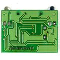
Schematic

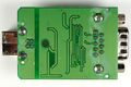
Photos
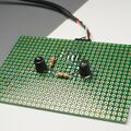
The IR diode and phototransistor are prominent on the board
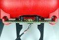
Board being held in place by the rubber holster


Brymen BC-85Xa interface cable
This is the official interface cable sold by Brymen. It works with the BM857a and BM859a, but does not work with thw non-a models.
Reverse engineering the cable
It is clear at this point that the protocol on the RS-232 side is not the same as the protocol used on the IR side. This raises an interesting question: Can the protocol be reversed-engineered and implemented as a simple UART? If the IR encoding is a simple UART, then it is feasible. A "brymen-dmm-raw" driver could provide users with a quick way to put together a circuit and communicate with their Brymen.
Connector pinout
| RS232 pin | Conductor pin
|
|---|---|
| 1 - DCD | NC |
| 2 - Rx | 7 - Red |
| 3 - Tx | 6 - Yellow |
| 4 - DTR | 5 - Green |
| 5 - GND | 1 - Blue |
| 6 - DSR | 4 - Gray |
| 7 - RTS | 3 - White |
| 8 - CTS | 2 - Black |
| 9 - RI | NC |
Infrared Signal
I thought it would be interested to see how the signal at the IR LED looks like. Since I didn't have an oscilloscope or logic analyzer available at the time, I used my sound card to record the signal. The AC coupling of the sound card makes the signal look funny, but the edges are clearly visible.
The first pulse is about 9ms long, while the second pulse is 10ms long. The two pulses are spaced 265ms apart. It looks as if the communication may be pulse-width based. Without having a cable/multimeter set that works, it is impossible to say more.
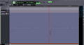
Signal at IR LED with vendor software attempting to connect. (AC coupled)

Photos
These are from the Extech SW810a kit. The components are all manufactured by Brymen, and carry the Brymen part numbers.
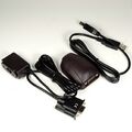
Kit contents (software disc not shown)
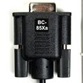
BC-85Xa DB9 connector
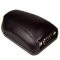
BC-85Xa DMM connector
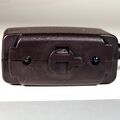
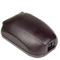
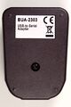
BUA2303 USB-to-serial converter
BUA2303 USB-to-serial converter, back
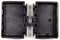
BUA2303 USB-to-serial converter, bottom
IR side, opened
IR side casing
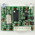
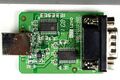
IR side PCB, top
IR side PCB, botoom
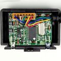
BUA2303 PCB, top
BUA2303 PCB, bottom


