Protocol decoder:ieee488
 | |
| Name | IEEE-488 |
|---|---|
| Description | IEEE-488 General Purpose Interface Bus (GPIB/HPIB or IEC). |
| Status | supported |
| License | GPLv2+ |
| Source code | decoders/ieee488 |
| Input | logic |
| Output | ieee488 |
| Probes | DIO1/DATA |
| Optional probes | DIO2-DIO8, EOI, DAV, NRFD, NDAC, IFC, SRQ, ATN, REN, CLK |
| Options | atn_parity, delim, iec_periph |
The ieee488 protocol decoder can decode either the parallel GPIB/HPIB bus (8 data and up to 8 control lines) or the serial IEC variant (clock and data, one line each).
While the internal implementation of the decoder marks most input signals as optional (to cover both serial and parallel variants), in practice some of the optional lines are essential for proper operation and just don't apply to the other main variant. For serial communication, DATA and CLK as well as ATN are required. For parallel communication DIO1 to DIO8 as well as DAV and ATN are required, and EOI is rather useful and shall get provided.
Parameters
- atn_parity, boolean: Whether DIO8 holds parity information for ATN commands.
- delim, enum: Payload data delimiter.
- iec_periph, boolean: Whether to decode Commodore IEC bus peripherals details (disk drives).
Example interactive use
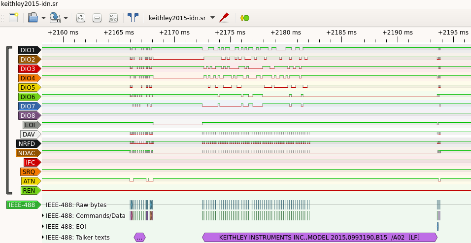
$ pulseview -i keithley2015/keithley2015-idn.sr
Example command line use
$ PD_PINS="dio1=DIO1:dio2=DIO2:dio3=DIO3:dio4=DIO4:dio5=DIO5:dio6=DIO6:dio7=DIO7:dio8=DIO8:eoi=EOI:dav=DAV:nrfd=NRFD:ndac=NDAC:ifc=IFC:srq=SRQ:atn=ATN:ren=REN"
$ sigrok-cli -i keithley2015/keithley2015-idn.sr -P ieee488:$PD_PINS -A ieee488=texts
ieee488-1: *idn?[CR][LF]
ieee488-1: KEITHLEY INSTRUMENTS INC.,MODEL 2015,0993190,B15  /A02  [LF]
Custom GPIB traffic capture hardware
Recording parallel GPIB communication for analysis involves sampling up to 16 digital lines at a rate of a few MHz. FX2 eval boards with two pin banks broken out are an easily available option, see the Lcsoft_Mini_Board for an example. But any other logic analyzer with 16 channels will do.
Connect the GPIB signals DIO1 through DIO8 to the FX2 pins B0 through B7. Connect signals EOI through REN to FX2 pins D0 through D7. Passing GPIB signals to the decoder in this very order is not strictly required, but convenient.
| GPIB signal | LA channel | FX2 pin |
|---|---|---|
| DIO1 | 0 | B0 |
| DIO2 | 1 | B1 |
| DIO3 | 2 | B2 |
| DIO4 | 3 | B3 |
| DIO5 | 4 | B4 |
| DIO6 | 5 | B5 |
| DIO7 | 6 | B6 |
| DIO8 | 7 | B7 |
| EOI | 8 | D0 |
| DAV | 9 | D1 |
| NRFD | 10 | D2 |
| NDAC | 11 | D3 |
| IFC | 12 | D4 |
| SRQ | 13 | D5 |
| ATN | 14 | D6 |
| REN | 15 | D7 |
Starting acquisition with the "probe names" option for the capture device simplifies the assignment of protocol decoder inputs. In the following example invocation the assignment will be done automatically. Users still need to adjust the samplerate and the samples count, and optionally specify a trigger condition. But the tedium of naming channels and assigning logic traces to decoder signals is out of the way.
$ pulseview -d fx2lafw:probe_names=ieee488 &
Resources
- Wikipedia IEEE-488 HP-IB / GPIB parallel bus
- Wikipedia Commodore Bus (IEC aka Standard Serial)
- pagetable.com Commodore Peripheral Bus article series by Michael Steil, github Markdown sources repo
