HYELEC MS8236
|
| |
| Status | planned |
|---|---|
| Counts | 6000 |
| IEC 61010-1 | CAT III (1000V) / CAT IV (600V) |
| Connectivity | USB |
| Measurements | voltage, resistance, diode, capacitance, frequency, current, hFE, temperature |
| Features | autorange, true-rms, data hold, delay hold, min/max, relative, bargraph, backlight |
| Website | hy-elec.com |
The HYELEC MS8236 is a 6000 counts, CAT III (1000V) / CAT IV (600V) handheld digital multimeter with USB connectivity.
See HYELEC MS8236/Info for more details (such as lsusb -v output) about the device.
Hardware
- 8-bit MCU with 4x40 LCD driver and 18-bit ADC: Hycontek HY11P14 (datasheet, user's guide)
- USB to serial IC: WCN CH340G (datasheet)
Photos
Multimeter:
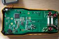
PCB, top
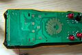
PCB, bottom
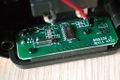
USB interface


USB cable:
Standard USB to miniUSB.
Protocol
TODO.
The device's LCD segments are layed out as follows:
| G | ||
| C | F | |
| B | ||
| A | E | |
| D |
To the left of each LCD digit there is another segment which represents a dot / decimal point (DP).
An LCD segment is represented in the protocol as follows:
| Bit 7 | Bit 6 | Bit 5 | Bit 4 | Bit 3 | Bit 2 | Bit 1 | Bit 0 |
|---|---|---|---|---|---|---|---|
| DP | A | B | C | D | E | F | G |
Example: In the protocol a byte of 0x3F (0 0111111) represents the digit 9 on the LCD, where the decimal point is not displayed (bit 7 is not set). All other bits except for bit 6 (segment A, see above) are set, i.e. the respective LCD segments are displayed.
The meter have an NCV icon but the function is not documented on the manual, I wasn't able to trigger it, it's probably not implemented. Everything with a (?) after is doubtful or impossible to confirm.
Protocol consists of 22 bytes:
Bytes 1 to 6: Always AA 55 52 24 01 10 . Probably some kind of header to test if transmission is ok, as the protocol doesn't have any kind of CRC.
Bytes 7 to 10: Next four bits are the big LCD numbers, from right to left, in the format already specified by uwe_ on the wiki.
Byte 11: 00000000 -> Diode icon
        |||||||---> AC
        ||||||----> DC
        |||||-----> -
        ||||------> - (yeah, both bits set to 1 when displaying "minus")
        |||-------> "Progess bar cue" -the bar with the 0 - 10 - 20 - ...
        ||--------> Continuity tester "sound" icon
        |---------> Battery
Bytes 12 to 18: that "progress bar on the top". Dunno what's its use, probably we can ignore it
Byte 19: 00000000 -> More progress bar thingy
        |||||||---> More progress bar thingy
        ||||||----> More progress bar thingy
        |||||-----> More progress bar thingy
        ||||------> Wait... (?) (Never shown on the PC but as it is a LCD protocol probably goes mapped here internally even if it never get transmited to the PC)
        |||-------> Auto
        ||--------> HOLD (?) (USB transmission seems to stop when Hold is activated)
        |---------> REL
Byte 20: 00000000 -> USB Icon (Of course, always on)
        |||||||---> MAX
        ||||||----> - (between MAX and MIN)
        |||||-----> MIN
        ||||------> N/A (?)
        |||-------> %
        ||--------> hFE
        |---------> N/A (?)
Byte 21: 00000000 -> C
        |||||||---> F (temp)
        ||||||----> N/A (?)
        |||||-----> N/A (?)
        ||||------> m (in the Farads line)
        |||-------> u (in the Farads line)
        ||--------> n (in the Farads line)
        |---------> F (Farads)
Byte 22: 00000000 -> u (in the A line)
        |||||||---> m (in the A line)
        ||||||----> A
        |||||-----> V (in diode meter mode)
        ||||------> M (in the Ohms line)
        |||-------> k (in the Ohms line)
        ||--------> Ohms
        |---------> Hz