fx2grok
The fx2grok family consists of four devices (fx2grok-flat, fx2grok-tiny, fx2grok-bga, fx2grok-wide) of very small, Open Hardware FX2-based logic analyzers.
The schematics and layouts are done from scratch in KiCad, and are released under the CC-BY-SA 4.0 license.
Using the open-source fx2lafw firmware (and sigrok, of course) you can use these devices as 8-channel (or 16-channel, for the fx2grok-wide) logic analyzers.
Device comparison
Note: Most of this is work in progress and might change at any time!
| Item | fx2grok-flat | fx2grok-tiny | fx2grok-bga | fxgrok-wide |
|---|---|---|---|---|
| Goals 2 |
|
|
|
|
| Author | Piotr Esden-Tempski | Uwe Hermann | Uwe Hermann | Ryan "Izzy" Bales, based off of Piotr Esden-Tempski's fx2grok-flat |
| Status | in progress | finished | WIP | WIP |
| Hardware license | CC-BY-SA 4.0 | CC-BY-SA 4.0 1 | CC-BY-SA 4.0 | CC-BY-SA 4.0 |
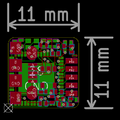
| Size | 33 mm x 16 mm | 11 mm x 11 mm | tbd | tbd |
| Logic channels | 8 + CLK & TRIG | 8 | tbd | 16 |
| Layout specs |
|
|
tbd | tbd |
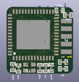
| Cypress FX2 | Cypress CY7C68013A-56LTXC, QFN, 8 mm x 8 mm | Cypress CY7C68013A-56LTXC, QFN, 8 mm x 8 mm | Cypress CY7C68013A-56BAXC, BGA, 5 mm x 5 mm | Cypress CY7C68013A-56LTXC, QFN, 8 mm x 8 mm |
| Input protection | 3 x IP425x-4-TTL EMI/ESD filters on all probes + 100k pull-ups, 1x USBLC6-2 for USB | None whatsoever | None whatsoever | 100Ω on each probe, 4x DSILC6-4 for all probes, 1x USBLC6-2 for USB |
| 24 MHz crytal | ABM8 | 4-SMD, 300μW, 2 mm x 1.6 mm | tbd | tbd |
| USB connector | USB Micro-B SMD | USB Micro-B SMD | tbd | USB Micro-B SMD |
| Probe connector | 2x6 1.27 mm PCB-edge connector | 2x5 1.27 mm PCB-edge connector | tbd | 2x 2x5 1.27 mm PCB-edge connectors |
| EEPROM | Yes, sigrok fx2lafw (8-channel) VID/PID 1d50:608c | None, default Cypress VID/PID 04b4:8613 | None, default Cypress VID/PID 04b4:8613 | Yes, sigrok fx2lafw (16-channel) VIP/PID 1d50:608d |
| Passives | Mostly 0402, some 0603 & 0.4 mm pitch DFN | Only 0402 | tbd | Mostly 0402, some 0603 |
| LED | 1x 0603 LED on PA1 | 1x 0402 LED on PA1 | tbd | 1x 0603 LED on PA1 |
1 The obsolete/nonworking fx2grok-tiny 0.1 was licensed CC-BY-SA 3.0, since version 0.2 the license is CC-BY-SA 4.0.
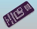
2 Optional goal: Make a tiny 3D-printed enclosure, and/or an "enclosure" using resin (example) with the device (including probes) ideally looking similar to the sigrok logo in the end.
What is NOT the goal?
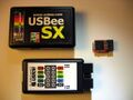
As you may know, there are tons of FX2-based logic analyzers (and tons of clones) already. There's not much use in creating yet another "standard" device.
The goal of these projects is thus NOT necessarily to make a better device, or to make a cheaper device, or anything like that. The main goals are to to make them Open Hardware and to have them be as tiny as possible (they're mostly "just for fun" projects, especially the fx2grok-tiny and fx2grok-bga variants).
Download
The schematics, PCB layout and Gerber files are available from the fx2grok Git repository:
$ git clone git://sigrok.org/fx2grok
fx2grok-tiny
Status
fx2grok-tiny 0.2 has been tested and is known to work. The first PCB version (fx2grok-tiny 0.1) is not working and thus obsolete.
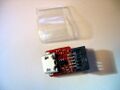
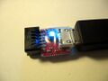
Photos
Schematics, PCB layout, 3D preview
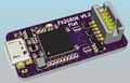
fx2grok-tiny 0.2:

Schematics
PCB layout
3D preview, top
3D preview, bottom
Connector pinout


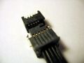
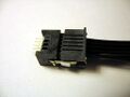
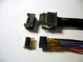
Cable and connector variants
Samtec SFSD-05-28-H-10.00-SR + TFM-105-01-L-D:
Samtec SFSD-05-28-H-10.00-SR
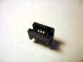
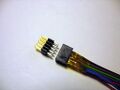
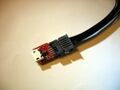
Connector with notch
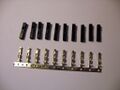
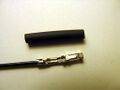
Crimp parts
Crimp
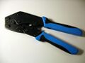
Crimp tool
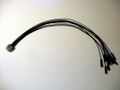
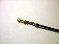
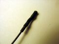
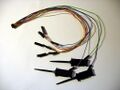
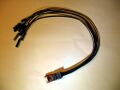
Finished cable
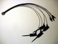
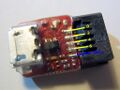
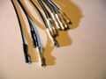
Cable with probes
Heatshrink tube variant
Heatshrink tube variant
Heatshrink tube variant
Heatshrink tube cable
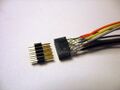
Samtec TFM-105-01-L-D
Samtec TFM-105-01-L-D
Cable connected
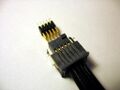
Cable + pinheader


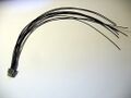
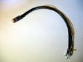
Hand-soldered ribbon cable:
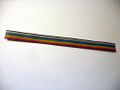
Ribbon cable
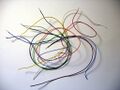
Individual wires
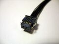
Soldered connector
Kapton tape
Finished cable
Cable comparison


Housing
Heatshrink tube
Heatshrink tube, LED


Assembly
The current set of red PCBs was manufactured by firstpcb.com, solder stencils are manufactured by oshstencils.com. You can use other PCB manufacturers of course, but don't forget that the PCB thickness must be 0.8mm (otherwise the probe connector won't fit) and that your PCB manufacturer must support all other specs (see table above).
The device can be assembled without too much hassle even though all parts are 0402 or otherwise very tiny.
- Apply solderpaste with the stencil to one PCB side.
- Place the parts with a pair of tweezers on the solderpaste (steady hands help, but no microscope is required).
- Solder the parts (a Puhui T-962A oven was used in this case; it should also be doable with a hot air gun/station or a modified pizza oven, though).
- Put some kapton tape on the soldered parts to prevent them from falling off while soldering the other PCB side in the oven.
- Apply solderpaste with the stencil to the other PCB side, place the parts, solder in the oven again.
- As a last step, manually solder (soldering iron) the 5x2 pins edge connector.
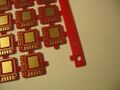
PCB panel
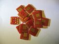
PCBs
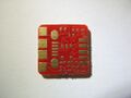
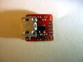
PCB, top
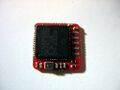
PCB, bottom
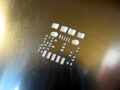
Stencil, top
Stencil, bottom
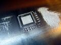
Solderpaste
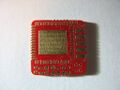
PCB, top, populated
PCB, bottom, populated
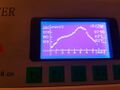
Example solderprofile
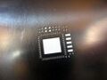
Device, top
Device, bottom
Device and cable
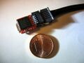
Size comparison


Bill of materials
Note: All prices are for single quantities, most parts get a lot cheaper if you buy higher quantities.
| Qty | Device | Footprint | Size | Value | Refdes | Digikey | Mouser | Comments |
|---|---|---|---|---|---|---|---|---|
| Required parts | ||||||||
| 1 | Cypress CY7C68013A-56LTXC | QFN-56 | 8 mm x 8 mm | — | IC1 | 10.05€ | 10.30€ | Main chip. Alternatives:
|
| 1 | Amphenol FCI 10118192-0001LF | custom | 9.8 mm x 5.6 mm | — | U1 | 0.38€ | 0.35€ | USB Micro-B SMD connector |
| 1 | Murata XRCGB24M000FAN00R0 | custom | 2 mm x 1.6 mm | 24 MHz | Y1 | 0.29€ | 0.46€ | 24MHz crystal, ±25ppm, 6pF, 150 Ohms, max. 300μW drive level, 4-SMD, no lead |
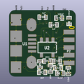
| 1 | Micrel MIC5504-3.3YM5-TR | SOT-23-5 | 2.9 mm x 1.6 mm | 3.3 V | U2 | 0.10€ | 0.10€ | 3.3 V LDO, max. 300mA |
| 4 | Yageo RC0402JR-072R7L | 0402 | 0.25 mm x 0.125 mm | 2.7 kΩ | R2, R3, R4, R5 | 0.08€ | 0.08€ | Resistor |
| 1 | Samsung RC1005J104CS | 0402 | 0.25 mm x 0.125 mm | 100 kΩ | R1 | 0.08€ | — | Resistor |
| 8 | Samsung CL05A104KP5NNNC | 0402 | 0.25 mm x 0.125 mm | 100 nF | C2, C5, C7, C8, C10-C13 | 0.08€ | — | Ceramic capacitor |
| 3 | Taiyo Yuden JMK105BJ105KV-F | 0402 | 0.25 mm x 0.125 mm | 1 µF | C1, C14, C16 | 0.08€ | 0.10€ | Ceramic capacitor |
| 2 | Murata GRM155R61A225KE95D | 0402 | 0.25 mm x 0.125 mm | 2.2 µF | C3, C6 | 0.08€ | 0.08€ | Ceramic capacitor |
| 2 | Samsung CL05C120JB5NNNC | 0402 | 0.25 mm x 0.125 mm | 12 pF | C4, C9 | 0.08 | — | Ceramic capacitor |
| 1 | Vishay VLMB1500-GS08 | 0402 | 0.25 mm x 0.125 mm | — | D1 | 0.34€ | 0.51€ | LED. When using other LED colors, you might also want a lower value for R5. |
| Optional parts / variants | ||||||||
| 1 | Amphenol FCI 20021111-00010T4LF | custom | — | — | P1/P2 | 0.53€ | 0.55€ | 5x2 through-hole pin header (1.27 mm pitch), could soldered to the PCB (5 pins per side) |
| 1 | Amphenol FCI 20021311-00010T4LF | custom | — | — | — | 0.68€ | 0.69€ | 5x2 connector/receptacle (1.27 mm pitch), could be used for soldering the probe cable/wires |
| 1 | Samtec TFM-105-01-L-D | custom | — | — | P1/P2 | 0.53€ | — | 5x2 through-hole pin header (1.27 mm pitch) with a notch, soldered to the PCB (5 pins per side), match for the Samtec SFSD-05-28-H-10.00-SR cable below |
| 1 | Samtec SFSD-05-28-H-10.00-SR | custom | — | — | — | 4.77€ | — | Potential probe cable, needs some crimping |
Note: C15 is missing and there is a C16, which is correct. C15 was removed and the numbering wasn't reset.
Random notes
- No, you cannot order assembled fx2grok-tiny devices or the bare PCBs anywhere, this is a pure hobby project. You can, however, make your own devices. Everything is Open Hardware, Open Source, and documented.
- The fx2grok-tiny device sacrifices a lot of things in order to make it as tiny as possible:
- There's no input protection whatsoever on the probes, not even a simple resistor. This means (among other things) you'll see random garbage on unconnected probes (which can be avoided by explicitly attaching them to a GND, though).
- There's no protection circuitry whatsoever on the USB side either.
- The device has no EEPROM, so it'll enumerate with the default Cypress USB VID/PID of 04b4:8613. libsigrok/fx2fwla currently assume all such devices are plain FX2 eval boards with all 16 channels accessible. However, fx2grok-tiny only has 8 channels on the connector, so until we have a nicer permanent fix for this, you have to either limit your samplerate to 12MHz (you cannot use 16MHz or 24MHz), or you can patch the libsigrok fx2lafw driver to treat devices with a VID/PID of 04b4:8613 as 8-channel devices (instead of 16-channel devices):
diff --git a/src/hardware/fx2lafw/api.c b/src/hardware/fx2lafw/api.c
index 34c5bc41..1634635a 100644
--- a/src/hardware/fx2lafw/api.c
+++ b/src/hardware/fx2lafw/api.c
@@ -70,7 +70,7 @@ static const struct fx2lafw_profile supported_fx2[] = {
         */
        { 0x04B4, 0x8613, "Cypress", "FX2", NULL,
                "fx2lafw-cypress-fx2.fw",
-               DEV_CAPS_16BIT, NULL, NULL },
+               0, NULL, NULL },
- Many of the recommendations from the Cypress FX2 datasheets and guides are ignored on the fx2grok-tiny (mostly in order to be able to make it smaller, sometimes also a bit simpler). While this seems to work fine regardless (for now), you shouldn't be too surprised if there are issues eventually.
- Unused pins should be tied to GND as per vendor (this is not done, though).
- The recommended crystal should have 12 pF (5 percent tolerance) load capacitors, we're using a crystal that wants 6 pF as per datasheet.
- The recommended crystal should have 500 µW drive level, we're using one with 300 µW.
- Cypress recommends a 4 layer PCB (we use a 2 layer PCB) and various other PCB layout / solderability related things that we're ignoring.
- The solderpaste is a big solid area under the FX2 device, it would be a bit nicer to have that part be a checkerboard pattern (but it seems to work well enough like this, too).
- etc. etc.
- The Gerber files intentionally don't include silkscreen (not really needed, might be too tiny anyway, sometimes might increase PCB manufacturing costs). However, the silkscreen is "abused" in the KiCad files to generate nice 3D previews (see above) that can be helpful when assembling the device.
- The fx2grok-tiny device currently has a blue LED with a 2k7 resistor (R5), which is sufficiently bright. If you want to use other LED colors you might also want to use a lower resistor value to increase brightness.
fx2grok-flat
Status
fx2grok-flat 0.2 has been tested and is known to work, but is not yet the final version. Additional improvements will be implemented in version 0.3.
Photos
Schematics, PCB layout, 3D preview
fx2grok-flat 0.2:
3D preview, top
3D preview, bottom


Resources
- Cypress FX2 overview page
- CY7C68013A, CY7C68014A, CY7C68015A, CY7C68016A datasheet (PDF)
- EZ-USB Technical Reference Manual (TRM) (PDF)
- AN15456 - Guide to a Successful EZ-USB FX2LP Hardware Design (PDF)
- esden's series of videos on the fx2grok-flat design (schematics, PCB, with background information and almost a KiCad tutorial)
- esden's GitHub repository with the KiCad project files for the fx2grok-flat (in the "flat" branch)
- Ryan's GitHub repository with the KiCad project files for the fx2grok-wide (in the "wide" branch)