Circuits for barebone boards
This page describes which input protection / measuring circuits for barebone or other more minimal boards can be used.
Probing a circuit
Usually for a logic analyzer high input impedance (and low capacitance) is wanted, to influence the measured circuit as least as possible (don't put an additional capacitive load on it). On the other hand, one might want to use an R-C low-pass filter for the signal to block possible higher frequency spikes. If that is wanted or required, it is best to introduce an additional buffering IC that will then drive the load of the introduced capacity of the filter. This can not directly be advised for logic analyzers, but rather for analog instruments (oscilloscopes) that will usually be used in a bigger variety of cases with possibly more noise in the signal.
Input protection
Clamp circuits with resistor / Z-Diodes
A clamp circuit can be used, for example view below at Spiralbrain's Blog. When using Zener diodes instead of the normal diodes in Spiralbrain's blog we can get also a protection from negative voltages:
The circuit is shown here again with Zener diodes and numbering for fx2lafw pins:

. It works in the following way: Case 1: When we get a voltage over 3.3V, the overvoltage will get "absorbed" over the Zener diodes like with normal diodes normal forward-mode. Case 2: At negative voltages, the Zener effect will happen for a reverse flow from the 3.3V supply to pull up the negative input.
For boards based on the Cypress CY7C68013A and some others it can be discussed if 4.7V or 5V Zener Diodes are also okay, as the CY7C68013A is 5V I/O tolerant -- 5V supply could then be used from USB.
When doing all this, one should be aware that not all diodes might be sufficient, as they will also introduce a minor capacitance.
The Saleae Logic Analyzer uses a specific "ESD protection IC" ( ST DVIULC6-4SC6 ) which is essentially a pair of diodes for a slightly different type of clamping / input protection, one will then just have to connect each input line after the resistors to one of the input pins of this IC. However this might not be as cheap as simple diodes and not as easily available.
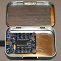
Lcsoft_Mini_Board inside a penguin peppermint tin box
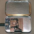
Lcsoft_Mini_Board inside a penguin peppermint tin box with added clamp circuit and connectors for probes on a breakout board
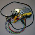
Lcsoft_Mini_Board inside a penguin peppermint tin box as an 8 channel logic analyzer


Issues measuring higher frequencies
When measuring something e.g. a 12 MHz Frequency (sampling @ 24MHz, so also just barely satisfying Nyquist-Shannon) that can push up to 20 pF load, the resistors in the mentioned circuit (4.7 k Ohm) together with "unknown" 3.6V Zener Diodes¹ might be too much load to overpower, the used test probes can also make an influence. Here is a comparison table which values were tried and how it turned out measuring a 12 MHz square wave:
¹) A 3.6 V Zener in reverse direction has a not-so-steep slope and is insufficient to protect from voltages < -0.5 V. A 3.3 V Zener diode has typical a capacity of 400 pF. With 4.7k resistor τ=1.88 µs the bandwidth is limited to approx 500 kHz.
| Resistor | Zener Diode | With test probes?12 | Measurement Result |
|---|---|---|---|
| 4.7 k Ohm | 3.6V | Cheap Test probe, longer wires | Only "high" |
| 890 Ohm | 3.6V (unknown speed) | Cheap Test probe, longer wires | Only "high" |
| 1.4 k Ohm | None | Short direct wires | Sometimes "high", about 75% correct |
| 100 Ohm | 3.6V | Cheap Test probe, longer wires | Sometimes "high", about 75% correct |
| 100 Ohm | None | Cheap Test probe, longer wires | Sometimes "high", about 90% correct |
| None | None | Cheap Test probe, longer wires | Sometimes "high", about 90% correct |
| None | None | Short direct wires | Sometimes "high", about 90% correct |
| None | 3.6V | Cheap Test probe, longer wires | Sometimes "high", about 90% correct |
Cheap Test probe made out of:
1 "Plastic Flat Multimeter Test Hook Clip Probes"
With buffer IC
Different buffer ICs can be used in combination with resistors (+ Z-Diodes to also protect the buffer IC). Depending on the IC, they can also be used for voltage-level conversion or clamping.
The 74HC241 can be driven at the measuring voltage up to 6V. Buffering can also be done by latch ICs like 74HC573 (3.3V) or 74HCT573 (5V).
Analog frontends
Designing a decent analog frontend to be used for example for fx2lafw capable devices will be a more complicated task. An appropriate ADC has to be found and an input stage with filter, protection and amplification elements needs to be designed. A possible ADC for up to 40MHz sampling frequency is the TDA 8703. An interesting project using that ADC with a parallel port can be found on volny.cz
You can also look at the analog frontend of the FX2 based EE Electronics ESLA201A or the better documented but more complex Nexus-Computing OsciPrime schematic there: [1]
For probes, an interesting DIY very high frequency probe can be found here at Douglas C. Smith Web Page