Difference between revisions of "Protocol decoder:Rfm12"
m |
Uwe Hermann (talk | contribs) m |
||
| (2 intermediate revisions by the same user not shown) | |||
| Line 1: | Line 1: | ||
{{Infobox protocol decoder | {{Infobox protocol decoder | ||
| id = rfm12 | | id = rfm12 | ||
| name = RFM12 | | name = RFM12 control protocol | ||
| description = | | description = HopeRF RFM12 wireless transceiver control protocol | ||
| status = supported | | status = supported | ||
| license = GPLv2+ | | license = GPLv2+ | ||
| source_code_dir = rfm12 | | source_code_dir = rfm12 | ||
| image = [[File:RFM12.png|250px]] | | image = [[File:RFM12.png|250px]] | ||
| input = spi | | input = [[Protocol decoder:spi|spi]] | ||
| output = rfm12 | | output = rfm12 | ||
| probes = — | | probes = — | ||
| optional_probes = — | | optional_probes = — | ||
| options = — | |||
}} | }} | ||
The '''rfm12''' decoder supports the control protocol for the | The '''rfm12''' decoder supports the control protocol for the [http://www.hoperf.com/rf/fsk_module/RFM12B.htm HopeRF RFM12] transceiver chip. | ||
== Hardware == | == Hardware == | ||
These modules | |||
RFM12B is a single chip, low power, multi-channel FSK transceiver designed for use in applications requiring FCC or ETSI conformance for unlicensed use in the 433MHz, 868MHz and 915MHz bands. | |||
These modules come in three different form factors, DIP package (shown on the photo in the upper right) and two SMD packages: S1 with normal crystal and S2 with low-profile crystal. | |||
<gallery> | |||
File:Hoperf rfm12bs top.jpg|<small>RFM12B-S, top</small> | |||
File:Hoperf rfm12bs bottom.jpg|<small>RFM12B-S, bottom</small> | |||
</gallery> | |||
Pins: | Pins: | ||
{| border="0" style="font-size: smaller" class="alternategrey sigroktable" | {| border="0" style="font-size: smaller" class="alternategrey sigroktable sortable" | ||
|- | |- | ||
!Name | !Name | ||
| Line 27: | Line 36: | ||
|- | |- | ||
| nINT/VDI | | nINT/VDI | ||
| Interrupt input (active low)/ | | Interrupt input (active low) / valid data indicator | ||
|- | |- | ||
| Line 55: | Line 64: | ||
|- | |- | ||
| FSK/DATA/nFFS | | FSK/DATA/nFFS | ||
| Transmit FSK data input/ | | Transmit FSK data input / received data output (FIFO not used) / FIFO select | ||
|- | |- | ||
| DCLK/CFIL/FFIT | | DCLK/CFIL/FFIT | ||
| | | Clock output (no FIFO) / external filter capacitor (analog mode) / FIFO interrupts (active high) | ||
interrupts(active high) | |||
|- | |- | ||
| Line 76: | Line 84: | ||
== Protocol == | == Protocol == | ||
SPI communication happens in a fixed length 16-bit chunks. During each exchange the microcontroller first sends the command and then receives the response. | In minimal configuration the chip uses the standard SPI protocol on pins SDI, SDO, SCK and nSEL. You can optionally connect nIRQ which will be pulled low by the transceiver to trigger interrupt requests. There is also an option to transmit and receive the data without the SPI protocol overhead using the dedicated DATA and DCLK pins. | ||
SPI communication happens in a fixed length of 16-bit chunks. During each exchange the microcontroller first sends the command and then receives the response. | |||
== Decoder == | == Decoder == | ||
The | The '''rfm12''' decoder stacks on top of the [[Protocol decoder:spi|SPI decoder]] and decodes the SPI exchanges. It shows what commands were sent to the chip and decodes the responses. It also interprets the commands and shows what happened to the chip. | ||
Some decoded commands in [[PulseView]]: | Some decoded commands in [[PulseView]]: | ||
| Line 92: | Line 101: | ||
== Resources == | == Resources == | ||
* [http://www.hoperf.com/rf/fsk_module/RFM12B.htm RFM12 page on HopeRF site] | * [http://www.hoperf.com/rf/fsk_module/RFM12B.htm RFM12 page on HopeRF site] | ||
* [http://www.hoperf.com/upload/rf/RFM12.pdf RFM12 datasheet] | * [http://www.hoperf.com/upload/rf/RFM12.pdf RFM12 datasheet] | ||
Latest revision as of 00:56, 3 April 2015
 | |
| Name | RFM12 control protocol |
|---|---|
| Description | HopeRF RFM12 wireless transceiver control protocol |
| Status | supported |
| License | GPLv2+ |
| Source code | decoders/rfm12 |
| Input | spi |
| Output | rfm12 |
| Probes | — |
| Optional probes | — |
| Options | — |
The rfm12 decoder supports the control protocol for the HopeRF RFM12 transceiver chip.
Hardware
RFM12B is a single chip, low power, multi-channel FSK transceiver designed for use in applications requiring FCC or ETSI conformance for unlicensed use in the 433MHz, 868MHz and 915MHz bands.
These modules come in three different form factors, DIP package (shown on the photo in the upper right) and two SMD packages: S1 with normal crystal and S2 with low-profile crystal.
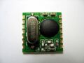
RFM12B-S, top
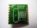
RFM12B-S, bottom


Pins:
| Name | Function |
|---|---|
| nINT/VDI | Interrupt input (active low) / valid data indicator |
| VDD | Positive power supply |
| SDI | SPI data input |
| SCK | SPI clock input |
| nSEL | Chip select (active low) |
| SDO | SPI data output |
| nIRQ | Interrupt request output (active low) |
| FSK/DATA/nFFS | Transmit FSK data input / received data output (FIFO not used) / FIFO select |
| DCLK/CFIL/FFIT | Clock output (no FIFO) / external filter capacitor (analog mode) / FIFO interrupts (active high) |
| CLK | Clock output for external microcontroller |
| nRES | Reset output (active low) |
| GND | Power ground |
Protocol
In minimal configuration the chip uses the standard SPI protocol on pins SDI, SDO, SCK and nSEL. You can optionally connect nIRQ which will be pulled low by the transceiver to trigger interrupt requests. There is also an option to transmit and receive the data without the SPI protocol overhead using the dedicated DATA and DCLK pins.
SPI communication happens in a fixed length of 16-bit chunks. During each exchange the microcontroller first sends the command and then receives the response.
Decoder
The rfm12 decoder stacks on top of the SPI decoder and decodes the SPI exchanges. It shows what commands were sent to the chip and decodes the responses. It also interprets the commands and shows what happened to the chip.
Some decoded commands in PulseView:
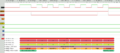
Status command.
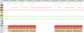
Receiver control command.
