Difference between revisions of "PoLabs PoScope Basic2"
Uwe Hermann (talk | contribs) m |
(update links to vendor's product page) |
||
| Line 1: | Line 1: | ||
[[File:Polabs_poscope_basic2.png|thumb|right|PoLabs PoScope Basic2]] | [[File:Polabs_poscope_basic2.png|thumb|right|PoLabs PoScope Basic2]] | ||
The [ | The [https://www.poscope.com/product/poscope-basic-2/ PoLabs PoScope Basic2] is a 16-channel, 8MHz, USB-based logic analyzer (plus oscilloscope, signal/pattern generator, and more). | ||
See [[PoLabs PoScope Basic2/Info]] for some more details (such as '''lsusb -vvv''' output) on the device. | See [[PoLabs PoScope Basic2/Info]] for some more details (such as '''lsusb -vvv''' output) on the device. | ||
| Line 336: | Line 336: | ||
== Resources == | == Resources == | ||
* [https://www.poscope.com/product/poscope-basic-2/ product page] | |||
[[Category:Device]] | [[Category:Device]] | ||
Revision as of 20:15, 4 January 2020

The PoLabs PoScope Basic2 is a 16-channel, 8MHz, USB-based logic analyzer (plus oscilloscope, signal/pattern generator, and more).
See PoLabs PoScope Basic2/Info for some more details (such as lsusb -vvv output) on the device.
Hardware
- Silicon Labs C8051F32x: 8051-based microcontroller with USB and 10bit ADC (datasheet)
- Omron G3VM-401G: Analog switching MOS FET relay (datasheet)
- Analog Devices AD8544: CMOS RRIO quad general-purpose opamp (datasheet)
- Texas Instruments HC74 87K G4 A6EK (TODO)
Photos
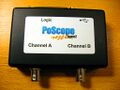
Device, top
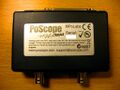
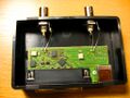
Device, bottom
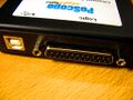
USB / LA connector
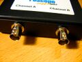
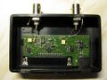
Analog connectors
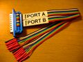
LA probe cable
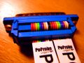
Probe cable details
PCB, front
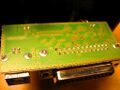
PCB, back
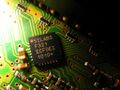
SiLabs F321
Analog Devices AD8544
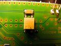
Omron G3VM-401G
TI HC74


Teardown of another device:
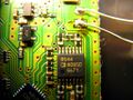
PCB, top
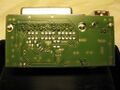
PCB, bottom
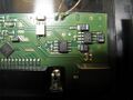
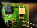
Chips


Protocol
Starting a sampling run
The command for starting an acquisition is a USB control transfer (request type: vendor-specific, request: 0x07, value: 0xffa0, index: 0x0000, length: 9).
The 9 bytes of data:
| Byte | Description | Comments |
|---|---|---|
| 0 | Samplerate divider | (see table below) |
| 1 | ||
| 2 | ||
| 3 | ||
| 4 | ||
| 5 | Trigger mask | Bit 0 is the mask for probe 0, bit 7 is the mask for probe 7. The same byte is used as trigger mask byte for bus A or bus B (only one at a time is possible). |
| 6 | ||
| 7 | ||
| 8 |
Stopping a sampling run
Sample rates
|
8MHz - 4MHz: Buffer size is 128 bytes, only bus A is available, ...
2.6MHz - 2MHz: Buffer size is 1160 bytes, only bus A is available, ...
1MHz - 600kHz: Buffer size is 1544 bytes, ...
|
500kHz and lower: Buffer size is only limited by the PC memory, ...
|
Sample format
- 8-bit sampling: One sample is one byte. Bit 0 is the value of probe A.7 (or B.7), bit 7 is the value of probe A.0 (or B.0).
- 16-bit sampling: One sample consists of two bytes. Byte 0 corresponds to bus A, byte 1 corresponds to bus B. The bit assignment is the same as above.
Buffer size
Pre-Trigger
Trigger settings
Get current firmware version
There is a command to request the current firmware version (and date) from the device. The device returns 5 bytes as response:
| Byte | Description | Comments |
|---|---|---|
| 0 | Major firmware version | Example: 0x03 means major version 3 (example version: 3.5). |
| 1 | Minor firmware version | Example: 0x05 means minor version 5 (example version: 3.5). |
| 2 | Firmware date (day) | Example: 0x1c means 28 (example date: 28/12/07). |
| 3 | Firmware date (month) | Example: 0x0c means 12 (example date: 28/12/07). |
| 4 | Firmware date (year, two digits) | Example: 0x07 means 2007 (example date: 28/12/07). |
So in the example of 0x03 0x05 0x1c 0x0c 0x07 the resulting firmware version/date is 3.5 (28/12/07).