Difference between revisions of "PoLabs PoScope Basic2"
Jump to navigation
Jump to search
Uwe Hermann (talk | contribs) |
Uwe Hermann (talk | contribs) m (→Sample rates) |
||
| Line 89: | Line 89: | ||
|- bgcolor="#6699ff" | |- bgcolor="#6699ff" | ||
!Samplerate | !Samplerate | ||
! | !Divider | ||
|- bgcolor="#eeeeee" | |- bgcolor="#eeeeee" | ||
| 8 MHz | | 8 MHz | ||
| | | 0x00 | ||
|- bgcolor="#dddddd" | |- bgcolor="#dddddd" | ||
| 6 MHz | | 6 MHz | ||
| | | 0x01 | ||
|- bgcolor="#eeeeee" | |- bgcolor="#eeeeee" | ||
| 4 MHz | | 4 MHz | ||
| | | 0x02 | ||
|} | |} | ||
| Line 108: | Line 108: | ||
|- bgcolor="#6699ff" | |- bgcolor="#6699ff" | ||
!Samplerate | !Samplerate | ||
! | !Divider | ||
|- bgcolor="#eeeeee" | |- bgcolor="#eeeeee" | ||
| 2.6 MHz | | 2.6 MHz | ||
| | | 0x03 | ||
|- bgcolor="#dddddd" | |- bgcolor="#dddddd" | ||
| 2 MHz | | 2 MHz | ||
| | | 0x04 | ||
|} | |} | ||
| Line 124: | Line 124: | ||
|- bgcolor="#6699ff" | |- bgcolor="#6699ff" | ||
!Samplerate | !Samplerate | ||
! | !Divider | ||
|- bgcolor="#eeeeee" | |- bgcolor="#eeeeee" | ||
| 1 MHz | | 1 MHz | ||
| | | 0x05 | ||
|- bgcolor="#dddddd" | |- bgcolor="#dddddd" | ||
| 900 kHz | | 900 kHz | ||
| | | 0x05 | ||
|- bgcolor="#eeeeee" | |- bgcolor="#eeeeee" | ||
| 800 kHz | | 800 kHz | ||
| | | 0x05 | ||
|- bgcolor="#dddddd" | |- bgcolor="#dddddd" | ||
| 700 kHz | | 700 kHz | ||
| | | 0x05 | ||
|- bgcolor="#eeeeee" | |- bgcolor="#eeeeee" | ||
| 600 kHz | | 600 kHz | ||
| | | 0x05 | ||
|} | |} | ||
| Line 149: | Line 149: | ||
|- bgcolor="#6699ff" | |- bgcolor="#6699ff" | ||
!Samplerate | !Samplerate | ||
! | !Divider | ||
|- bgcolor="#eeeeee" | |- bgcolor="#eeeeee" | ||
| 500 kHz | | 500 kHz | ||
| | | 0x05 | ||
|- bgcolor="#dddddd" | |- bgcolor="#dddddd" | ||
| 400 kHz | | 400 kHz | ||
| | | 0x05 | ||
|- bgcolor="#eeeeee" | |- bgcolor="#eeeeee" | ||
| 300 kHz | | 300 kHz | ||
| | | 0x05 | ||
|- bgcolor="#dddddd" | |- bgcolor="#dddddd" | ||
| 250 kHz | | 250 kHz | ||
| | | 0x06 | ||
|- bgcolor="#eeeeee" | |- bgcolor="#eeeeee" | ||
| 200 kHz | | 200 kHz | ||
Revision as of 00:41, 6 January 2012

The PoLabs PoScope Basic2 is a 16-channel, 8MHz, USB-based logic analyzer (plus oscilloscope, signal/pattern generator, and more).
See PoLabs PoScope Basic2/Info for some more details (such as lsusb -vvv output) on the device.
Components
- Silicon Labs C8051F32x: 8051-based microcontroller with USB and 10bit ADC (datasheet)
- Omron G3VM-401G: Analog switching MOS FET relay (datasheet)
- Analog Devices AD8544: CMOS RRIO quad general-purpose opamp (datasheet)
- Texas Instruments HC74 87K G4 A6EK (TODO)
Photos
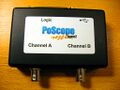
Device, top
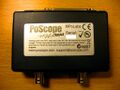
Device, bottom
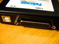
USB / LA connector
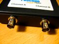
Analog connectors
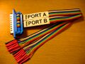
LA probe cable
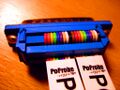
Probe cable details
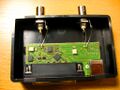
PCB, front
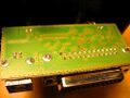
PCB, back
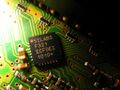
SiLabs F321
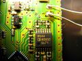
Analog Devices AD8544
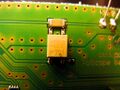
Omron G3VM-401G
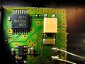
TI HC74


Protocol
Starting a sampling run
The command for starting an acquisition seems to be a 9-byte sequence.
| Byte | Description | Comments |
|---|---|---|
| 0 | Samplerate divider | (see table below) |
| 1 | ||
| 2 | ||
| 3 | ||
| 4 | ||
| 5 | Trigger mask | Bit 0 is the mask for probe 0, bit 7 is the mask for probe 7. The same byte is used as trigger mask byte for bus A or bus B (only one at a time is possible). |
| 6 | ||
| 7 | ||
| 8 |
Stopping a sampling run
Sample rates
8MHz - 4MHz:
Buffer size is 128 bytes, only bus A is available, ...
| Samplerate | Divider |
|---|---|
| 8 MHz | 0x00 |
| 6 MHz | 0x01 |
| 4 MHz | 0x02 |
2.6MHz - 2MHz:
Buffer size is 1160 bytes, only bus A is available, ...
| Samplerate | Divider |
|---|---|
| 2.6 MHz | 0x03 |
| 2 MHz | 0x04 |
1MHz - 600kHz:
Buffer size is 1544 bytes, ...
| Samplerate | Divider |
|---|---|
| 1 MHz | 0x05 |
| 900 kHz | 0x05 |
| 800 kHz | 0x05 |
| 700 kHz | 0x05 |
| 600 kHz | 0x05 |
500kHz and lower:
Buffer size is only limited by the PC memory, ...
| Samplerate | Divider |
|---|---|
| 500 kHz | 0x05 |
| 400 kHz | 0x05 |
| 300 kHz | 0x05 |
| 250 kHz | 0x06 |
| 200 kHz | ... |
| 150 kHz | ... |
| 100 kHz | ... |
| 90 kHz | ... |
| 80 kHz | ... |
| 70 kHz | ... |
| 60 kHz | ... |
| 50 kHz | ... |
| 40 kHz | ... |
| 30 kHz | ... |
| 25 kHz | ... |
| 20 kHz | ... |
| 10 kHz | ... |
| 9 kHz | ... |
| 8 kHz | ... |
| 7 kHz | ... |
| 6 kHz | ... |
| 5 kHz | ... |
| 4 kHz | ... |
| 3 kHz | ... |
| 2.5 kHz | ... |
| 2 kHz | ... |
| 1 kHz | ... |