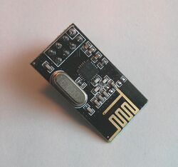
Protocol decoder:nrf24l01
 | |
| Name | nRF24L01(+) |
|---|---|
| Description | 2.4GHz transceiver chip |
| Status | supported |
| License | GPLv2+ |
| Source code | decoders/nrf24l01 |
| Input | spi |
| Output | nrf24l01 |
| Probes | — |
| Optional probes | — |
The nrf24l01 protocol decoder supports the protocol spoken by the Nordic Semiconductor nRF24L01 and nRF24L01+ 2.4GHz transceiver chips.
Hardware
Modules with these chips can be purchased fairly inexpensive from various online marketplaces. Most (all?) have an 8-pin header with the following pinout:
| Pin | Function |
|---|---|
| 1 | GND |
| 2 | VCC |
| 3 | CE |
| 4 | CSN |
| 5 | SCK |
| 6 | MOSI |
| 7 | MISO |
| 8 | IRQ |
The chip has two chip select pins, "CE" used to control the standby mode, and "CSN" used for SPI communication.
Protocol
The chip uses the standard SPI protocol and pins (CSN, SCK, MOSI, MISO), with the additional CE (used to control the RX/TX and standby modes) and IRQ (used to inform the SPI master about the completion of a packet reception/transmission) signals. If the number of available pins of the master are scarce, the CE pin can be tied to VCC and the IRQ pin can be left open. Polling over SPI can be used instead.
SPI commands can have variable length, the CSN signal has to stay low during the whole command, and then go high after the last byte. The first byte of a command defines the type of the command, the chip always outputs its internal status register at the beginning. The following bytes are dependent on the command type, can be register values to write into the chip or payload data to send, or empty bytes that are ignored if the command only reads the output of the chip.
Decoder
The nrf24l01 decoder stacks on top of the SPI decoder and decodes the commands to the chip and the responses of the chip, and also issues warnings for wrong/incomplete commands.
Some decoded commands in PulseView:
sigrok-cli can be used to decode the capture in the following way:
$ sigrok-cli -i sigrok-dumps/spi/nrf24l01/nrf24l01-communication.sr \
             -P spi:cs=rpi_CSN:clk=rpi_CLK:mosi=rpi_MOSI:miso=rpi_MISO,nrf24l01
Cmd. R_REGISTER "CONFIG"
Reg. STATUS = "\x0E"
Reg. CONFIG = "\x08"
Reg. STATUS = "\x0E"
Cmd. W_REGISTER: CONFIG = "\x08"
Reg. STATUS = "\x0E"
Cmd. W_REGISTER: RF_CH = "\x3E"
Reg. STATUS = "\x0E"
Cmd. W_REGISTER: RX_ADDR_P0 = "\x37\x67\x74\x36\x7E"
Reg. STATUS = "\x0E"
...
Cmd. R_RX_PAYLOAD
Reg. STATUS = "\x40"
RX payload = "message #0"
It can be seen that the register values are hex encoded, while the payload data is, if possible, represented as ASCII characters.
If only the payload is of interest, the tx-data and rx-data annotation classes can be selected using the -A|--protocol-decoder-annotations option:
$ sigrok-cli -i sigrok-dumps/spi/nrf24l01/nrf24l01-communication.sr \
             -P spi:cs=uc_CSN:clk=uc_CLK:mosi=uc_MOSI:miso=uc_MISO,nrf24l01 \
             -A nrf24l01=tx-data
TX payload = "message #0"
TX payload = "message #1"
TX payload = "message #2"
TX payload = "message #3"
TX payload = "message #4"
TX payload = "message #5"
TX payload = "message #6"
TX payload = "message #7"
TX payload = "message #8"
TX payload = "message #9"
$ sigrok-cli -i sigrok-dumps/spi/nrf24l01/nrf24l01-communication.sr \
             -P spi:cs=rpi_CSN:clk=rpi_CLK:mosi=rpi_MOSI:miso=rpi_MISO,nrf24l01 \
             -A nrf24l01=rx-data
RX payload = "message #0"
RX payload = "message #1"
RX payload = "message #2"
RX payload = "message #3"
RX payload = "message #4"
RX payload = "message #5"
Warnings issued for erroneous commands:
$ sigrok-cli -i sigrok-dumps/spi/nrf24l01/nrf24l01-test-missing-bytes.sr \
             -P spi:cs=CS:clk=CLK:mosi=MOSI:miso=MISO,nrf24l01
Cmd. R_REGISTER "CONFIG"
Reg. STATUS = "\x00"
missing data bytes
Cmd. W_TX_PAYLOAD_NOACK
Reg. STATUS = "\x00"
missing data bytes
Resources
- Nordic Semiconductor nRF24L01 (datasheet)
- Nordic Semiconductor nRF24L01+ (datasheet)
- github.com: nrf24l01 (various nRF24L01(+) projects and examples)


