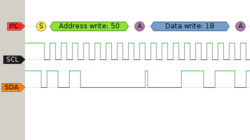
Protocol decoder:i2c
 | |
| Name | Inter-Integrated Circuit |
|---|---|
| Description | Two-wire, multi-master, serial bus |
| Status | supported |
| License | GPLv2+ |
| Source code | decoders/i2c |
| Input | logic |
| Output | i2c |
| Probes | SCL, SDA |
| Optional probes | — |
The i2c protocol decoder supports the Inter-Integrated Circuit (I²C) bidirectional, multi-master serial protocol.
Hardware
TODO.
Protocol
The Inter-Integrated Circuit (I²C) bus is a bidirectional, multi-master bus using two signals (SCL = serial clock line, SDA = serial data line).
There can be many devices on the same bus. Each device can potentially be master or slave (and that can change during runtime). Both slave and master can potentially play the transmitter or receiver role (this can also change at runtime).
Possible maximum data rates:
- Standard mode: 100 kbit/s
- Fast mode: 400 kbit/s
- Fast-mode Plus: 1 Mbit/s
- High-speed mode: 3.4 Mbit/s
Basic protocol:
- START condition: SDA = falling, SCL = high
- Repeated START condition: same as START condition
- Data bit sampling: SCL = rising
- STOP condition: SDA = rising, SCL = high
All data bytes on SDA are exactly 8 bits long (transmitted MSB-first). Each byte has to be followed by a 9th ACK/NACK bit. If that bit is low, that indicates an ACK, if it's high that indicates a NACK.
After the first START condition, a master sends the device address of the slave it wants to talk to. Slave addresses are 7 bits long (MSB-first). After those 7 bits, a data direction bit is sent. If the bit is low that indicates a WRITE operation, if it's high that indicates a READ operation.
Later an optional 10bit slave addressing scheme was added.