Saleae Logic
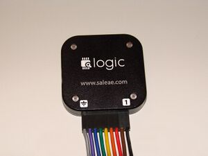
The Saleae Logic is a 24MHz, 8-channel, USB-based logic analyzer.
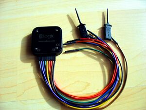
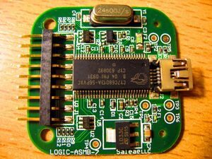
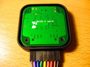
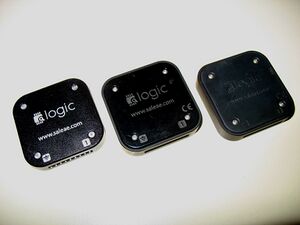
The unit itself is very small, and has a USB 2.0 port connecting it to a PC (and powering the unit) and a connector for the 8 + 1 probe set. It is built around a Cypress EZ-USB FX2LP microcontroller — an 8051-compatible chip with built-in USB 2.0 controller. It can sample 8 channels up to 24MHz and sells for $150.
The Saleae Logic reports on the USB bus with vendor ID 0x0925, product ID 0x3881 (see also the full lsusb). It has no firmware on board; this must be uploaded when the unit is powered on. sigrok uses the fx2lafw firmware for this.
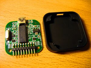
The case has four Torx T2 screws you need to remove in order to be able to open it.
See Saleae Logic/Info for more details (such as lsusb -vvv output) about the device.
See Saleae Logic16 for the successor product of the Saleae Logic.
Components
- Main chip: Cypress CY7C68013A-56PVXC (SSOP)
- ESD protection: ST DVIULC6-4SC6
- 3.3V voltage regulator: ST LD33C
- I2C EEPROM: Unknown (marking: M0KS / MOKS)
- Crystal: 24MHz
Saleae firmware protocol
The original Saleae firmware, no longer used in sigrok, announces itself on the USB bus with the same vendor and product IDs, but with two endpoints: endpoint 1 (out) is used for sending commands to the logic analyzer, endpoint 2 (in) is for transfers of sample sets. Both endpoints are of type bulk.
The Saleae Logic does no analysis in hardware at all. Processing triggers, protocol analysis and so on is all done on the software side; the hardware unit merely sends the requested number of samples at a given sample rate. The device has 8 probes, all of which are always probed and sent along. A full sample is thus always exactly one byte.
Setting the samplerate, starting an acquisition
There is only one command the software sends to the Saleae Logic on endpoint 1: a two-byte command to set the samplerate. The first byte is always 0x01 (0xd5 on more recent firmware versions). This is likely a command opcode meaning "set sample rate".
The second byte indicates the samplerate. The samplerate is given in the form of a divider based on the FX2LP's clock, which runs at 48MHz. The following formula is used:
samplerate = 48 / (1 + divider)
Thus, a samplerate of 2 MHz (for example) is selected by using 23 as the divider:
| 1st byte | 2nd byte |
|---|---|
| 0x01 (1) | 0x17 (23) |
Supported samplerates
The following samplerates are supported in older firmware versions:
| Samplerate | Divider (hex) | Divider (int) |
|---|---|---|
| 200 kHz | 0xef | 239 |
| 250 kHz | 0xbf | 191 |
| 500 kHz | 0x5f | 95 |
| 1 MHz | 0x2f | 47 |
| 2 MHz | 0x17 | 23 |
| 4 MHz | 0x0b | 11 |
| 8 MHz | 0x05 | 5 |
| 12 MHz | 0x03 | 3 |
| 16 MHz | 0x02 | 2 |
| 24 MHz | 0x01 | 1 |
Recent versions of the vendor software have additional samplerate settings of 100 kHz, 50 kHz, and 25 kHz. However, these result in the same divider value of 239 (and the software likely just uses every 2nd/4th/8th sample) as with the 200 kHz samplerate, so they're not really too useful.
The following samplerates are supported in newer firmware versions:
| Samplerate | Divider (hex) | Divider (int) |
|---|---|---|
| 200 kHz | 0x4e | 78 |
| 250 kHz | 0x9e | 158 |
| 500 kHz | 0xfe | 254 |
| 1 MHz | 0x8e | 142 |
| 2 MHz | 0xe6 | 230 |
| 4 MHz | 0xda | 218 |
| 8 MHz | 0xd4 | 212 |
| 12 MHz | 0xe2 | 226 |
| 16 MHz | 0xd5 | 213 |
| 24 MHz | 0xe0 | 224 |
Getting samples
Samples are read off endpoint 2. The Saleae Logic receives a read request from the host, and responds by sending the requested number of samples. The maximum number of samples transferred at a time is 4096, a constraint in the USB protocol. A sample is one byte, with each bit representing the state of one of the probes. Probe 1 (black wire) is in the MSB of the sample, probe 8 (purple wire) is the LSB.
