Difference between revisions of "Hantek DDS-3X25"
Jump to navigation
Jump to search
| Line 19: | Line 19: | ||
== Protocol == | == Protocol == | ||
{| border="0" width="95%" style="font-size: smaller" class="alternategrey sigroktable" | |||
|- | |||
! style="width: 3em;" | Command | |||
! style="width: 3em;" | Byte | |||
! style="width: 3em;" | Bit | |||
! Description | |||
|- | |||
| valign="top" colspan="3" | 0XA0 | |||
| '''Configure''' | |||
|- | |||
| | |||
| 1 | |||
| | |||
| Mode | |||
|- | |||
| | |||
| | |||
| 7 | |||
| | |||
|- | |||
| | |||
| | |||
| 6 | |||
| | |||
|- | |||
| | |||
| | |||
| 5 | |||
| 1 = Reset external trigger (send only once) | |||
|- | |||
| | |||
| | |||
| 4 | |||
| 1 = External trigger mode enabled | |||
|- | |||
| | |||
| | |||
| 3 | |||
| External trigger: 0 = falling, 1 = rising | |||
|- | |||
| | |||
| | |||
| 2 | |||
| 0 = continuous, 1 = single wave | |||
|- | |||
| | |||
| | |||
| 1 | |||
| | |||
|- | |||
| | |||
| | |||
| 0 | |||
| Measurement: 0 = frequency, 1 = counter | |||
|- | |||
| | |||
| 2 | |||
| | |||
| | |||
|- | |||
| | |||
| | |||
| 7 | |||
| | |||
|- | |||
| | |||
| | |||
| 6 | |||
| | |||
|- | |||
| | |||
| | |||
| 5 | |||
| | |||
|- | |||
| | |||
| | |||
| 4 | |||
| | |||
|- | |||
| | |||
| | |||
| 3 | |||
| | |||
|- | |||
| | |||
| | |||
| 2 | |||
| | |||
|- | |||
| | |||
| | |||
| 1 | |||
| | |||
|- | |||
| | |||
| | |||
| 0 | |||
| Output: 0 = pattern generator, 1 = programmable output | |||
|- | |||
| | |||
| 3 | |||
| | |||
| Digital I/O pins, bits 0-7 | |||
|- | |||
| | |||
| 4 | |||
| | |||
| Bits 0-3 = digital I/O pins bits 8-11, bits 4-7 unused | |||
|- | |||
| | |||
| 5 | |||
| | |||
| Clock divider, based on 48KHz clock | |||
|- | |||
| | |||
| 6 | |||
| | |||
| | |||
|} | |||
[[Category:Device]] | [[Category:Device]] | ||
[[Category:Function generator]] | [[Category:Function generator]] | ||
[[Category:Planned]] | [[Category:Planned]] | ||
Revision as of 21:43, 5 April 2013
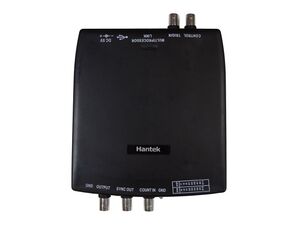
The Hantek DDS-3X25 is a 25MHz PC-based function generator. It has no external controls, requiring a USB connection to a computer.
Hardware
TODO.
Photos
Protocol
| Command | Byte | Bit | Description |
|---|---|---|---|
| 0XA0 | Configure | ||
| 1 | Mode | ||
| 7 | |||
| 6 | |||
| 5 | 1 = Reset external trigger (send only once) | ||
| 4 | 1 = External trigger mode enabled | ||
| 3 | External trigger: 0 = falling, 1 = rising | ||
| 2 | 0 = continuous, 1 = single wave | ||
| 1 | |||
| 0 | Measurement: 0 = frequency, 1 = counter | ||
| 2 | |||
| 7 | |||
| 6 | |||
| 5 | |||
| 4 | |||
| 3 | |||
| 2 | |||
| 1 | |||
| 0 | Output: 0 = pattern generator, 1 = programmable output | ||
| 3 | Digital I/O pins, bits 0-7 | ||
| 4 | Bits 0-3 = digital I/O pins bits 8-11, bits 4-7 unused | ||
| 5 | Clock divider, based on 48KHz clock | ||
| 6 | |||


