Difference between revisions of "Lcsoft Mini Board"
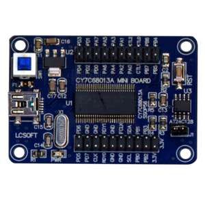
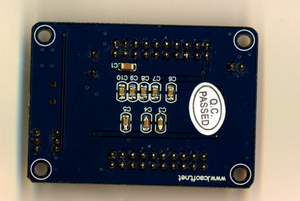
(Created page with 'thumb|right|Lcsoft CY7C68013A Mini Board thumb|right|Back of PCB This is a barebones development board for…') |
Bluesceada (talk | contribs) (added hardware extension info) |
||
| Line 11: | Line 11: | ||
The board is fully supported by sigrok, using the Saleae driver. | The board is fully supported by sigrok, using the Saleae driver. | ||
== Required Testing Hardware Extensions == | |||
'''Do not directly hook the board pins to another circuit, if you don't know what you are doing! This could damage the board!''' | |||
The simplest circuit would be adding at least resistors in between your circuit-in-test and the LCSoft board, but be aware here that this cypress chip can only tolerate a maximum of 5V I/O. Better would be to use a clamp circuit like shown at [http://sunbizhosting.co.uk/~spiral/blog/?p=117 Spiralbrain's Blog]. A buffer circuit using a 74HC241 IC for protection is also possible. Check on the [[fx2lafw]] page to see which protection circuits are used on other logic analyzer boards. | |||
Revision as of 13:05, 26 June 2012
This is a barebones development board for the Cypress FX2 chip, as used in the Saleae Logic and other boards. It is available on Ebay for less than €15, or Taobao for even less.
Hardware
All the pins on the FX2 are broken out to 40 header pins. There's an on/off toggle switch, a reset button, and a jumper that lets you select whether the FX2 gets its configuration from a small EEPROM, or boots into the default mode. The EEPROM's default settings make it come up with the same VID:PID as a Saleae board.
Driver
The board is fully supported by sigrok, using the Saleae driver.
Required Testing Hardware Extensions
Do not directly hook the board pins to another circuit, if you don't know what you are doing! This could damage the board!
The simplest circuit would be adding at least resistors in between your circuit-in-test and the LCSoft board, but be aware here that this cypress chip can only tolerate a maximum of 5V I/O. Better would be to use a clamp circuit like shown at Spiralbrain's Blog. A buffer circuit using a 74HC241 IC for protection is also possible. Check on the fx2lafw page to see which protection circuits are used on other logic analyzer boards.

