Difference between revisions of "RDing TEMPer"
Jump to navigation
Jump to search
Uwe Hermann (talk | contribs) m (→Hardware) |
Uwe Hermann (talk | contribs) m (→Photos) |
||
| Line 95: | Line 95: | ||
File:Rding temper pcb front.jpg|<small>PCB, front</small> | File:Rding temper pcb front.jpg|<small>PCB, front</small> | ||
File:Rding temper pcb back.jpg|<small>PCB, back</small> | File:Rding temper pcb back.jpg|<small>PCB, back</small> | ||
File:Rding temper sensor.jpg|<small>Sensor</small> | File:Rding temper sensor.jpg|<small>Sensor, EEPROM</small> | ||
File:Rding temper sidepads.jpg|<small>Random pads on the side</small> | File:Rding temper sidepads.jpg|<small>Random pads on the side</small> | ||
File:Rding temper main chip microscope.jpg|<small>Main chip, microscope</small> | File:Rding temper main chip microscope.jpg|<small>Main chip, microscope</small> | ||
Revision as of 14:10, 24 June 2012
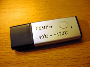
The RDing TEMPer is a USB-based temperature logger.
See RDing TEMPer/Info for more details (such as lsusb -vvv output) about the device.
Hardware
- Main chip: Unknown, yet (markings were removed)
- Temperature sensor: Fairchild FM75 (datasheet), I2C slave addres 0x4f
- I2C EEPROM: Unknown, yet (markings were removed), I2C slave addres 0x50
- Oscillator: 6MHz
Main chip pinout:
| 1 | 2 | 3 | 4 | 5 | 6 | 7 | 8 | 9 | 10 | 11 | 12 | 13 | 14 | 15 | 16 | 17 | 18 | 19 | 20 |
|---|---|---|---|---|---|---|---|---|---|---|---|---|---|---|---|---|---|---|---|
| SCL | SDA | 5V/high | 5V/high | 5V/high | 5V/high | GND | 5V/high | 3.3V | Oscillator | Oscillator | 5V/high | USB D- | USB D+ | LED (5V) | 5V | 3.3V | 3.3V |
I2C EEPROM pinout:
| 1 | 2 | 3 | 4 | 5 | 6 | 7 | 8 |
|---|---|---|---|---|---|---|---|
| GND | GND | GND | GND | SDA | SCL | GND | 3.3V |
Photos
Protocol
HID-based.


