Difference between revisions of "Protocol decoder:Uart"
Uwe Hermann (talk | contribs) m |
Uwe Hermann (talk | contribs) m |
||
| Line 3: | Line 3: | ||
| name = UART | | name = UART | ||
| description = Asynchronous, serial bus | | description = Asynchronous, serial bus | ||
| status = | | status = supported | ||
| license = GPLv2+ | | license = GPLv2+ | ||
| source_code_dir = uart | | source_code_dir = uart | ||
Revision as of 14:56, 3 August 2014
 | |
| Name | UART |
|---|---|
| Description | Asynchronous, serial bus |
| Status | supported |
| License | GPLv2+ |
| Source code | decoders/uart |
| Input | logic |
| Output | uart |
| Probes | — |
| Optional probes | RX, TX |
The uart protocol decoder (a.k.a. RS232) can decode the Universal asynchronous receiver/transmitter and similar asynchronous communication protocols with various baudrates, stop bit settings, parity settings and so on.
Hardware
V&A VA18B multimeter cable
The uart/v_and_a_va18b_cable directory in sigrok-dumps contains a set of example captures of the UART communication on the V&A VA18B multimeter PC cable (captured on the RX/TX pins of the Prolific PL2303HX chip in that cable). Additionally, it also contains the IR LED "probe" as well as USB D+/D- probes in the same capture.
The logic analyzer used was a Saleae Logic (at 16MHz).
Probe setup:
| Probe | Pin/chip |
|---|---|
| 1 (black) | IR LED |
| 2 (brown) | TX (PL2303HX) |
| 3 (red) | RX (PL2303HX) |
| 4 (orange) | USB DM |
| 5 (yellow) | USB DP |
Photos:
Protocol
Universal Asynchronous Receiver Transmitter (UART) is a simple serial communication protocol which allows two devices to talk to each other. It uses just two data signals and a ground (GND) signal:
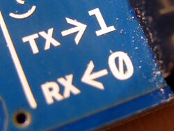
- RX/RXD: Receive signal
- TX/TXD: Transmit signal
The protocol is asynchronous, i.e., there is no dedicated clock signal. Rather, both devices have to agree on a baudrate (number of bits to be transmitted per second) beforehand. Baudrates can be arbitrary in theory, but usually the choice is limited by the hardware UARTs that are used. Common values are 9600 or 115200.
The protocol allows full-duplex transmission, i.e. both devices can send data at the same time. However, unlike SPI (which is always full-duplex, i.e., each send operation is automatically also a receive operation), UART allows one-way communication, too. In such a case only one signal (and GND) is required.
The data is sent over the TX line in so-called frames, which consist of:
- Exactly one start bit (always 0/low).
- Between 5 and 9 data bits.
- An (optional) parity bit.
- One or more stop bit(s).
The idle state of the RX/TX line is 1/high. As the start bit is 0/low, the receiver can continually monitor its RX line for a falling edge, in order to detect the start bit. Once detected, it can (due to the agreed-upon baudrate and thus the known width/duration of one UART bit) sample the state of the RX line "in the middle" of each (start/data/parity/stop) bit it wants to analyze.
It is configurable whether there is a parity bit in a frame, and if yes, which type of parity is used:
- None: No parity bit is included.
- Odd: The number of 1 bits in the data (and parity bit itself) is odd.
- Even: The number of 1 bits in the data (and parity bit itself) is even.
- Mark/one: The parity bit is always 1/high (also called 'mark state').
- Space/zero: The parity bit is always 0/low (also called 'space state').
It is also configurable how many stop bits are to be used:
- 1 stop bit (most common case)
- 2 stop bits
- 1.5 stop bits (i.e., one stop bit, but 1.5 times the UART bit width)
- 0.5 stop bits (i.e., one stop bit, but 0.5 times the UART bit width)
The bit order of the 5-9 data bits is usually LSB-first.
Possible special cases:
- One or both data lines could be inverted, which also means that the idle state of the signal line(s) is low instead of high.
- Only the data bits on one or both data lines (and the parity bit) could be inverted (but the start/stop bits remain non-inverted).
- The bit order could be MSB-first instead of LSB-first.
- The baudrate could change in the middle of the communication. This only happens in very special cases, and can only work if both devices know to which baudrate they are to switch, and when.
- Theoretically, the baudrate on RX and the one on TX could also be different, but that's a very obscure case and probably doesn't happen very often in practice.
Error conditions:
- If there is a parity bit, but it doesn't match the expected parity, this is called a parity error.
- If there are no stop bit(s), that's called a frame error.


