Difference between revisions of "LeCroy LogicStudio"
Uwe Hermann (talk | contribs) (LeCroy LogicStudio is supported.) |
Uwe Hermann (talk | contribs) (Mugshot) |
||
| Line 1: | Line 1: | ||
{{Infobox logic analyzer | {{Infobox logic analyzer | ||
| image = [[File:Lecroy | | image = [[File:Lecroy logicstudio16 mugshot.png|180px]] | ||
| name = LeCroy LogicStudio | | name = LeCroy LogicStudio | ||
| status = supported | | status = supported | ||
Revision as of 16:00, 11 December 2015
 | |
| Status | supported |
|---|---|
| Source code | lecroy-logicstudio |
| Channels | 16 |
| Samplerate | 1GHz (@ 8ch), 500MHz (@ 16ch) |
| Samplerate (state) | — |
| Triggers | high/low state, rising/falling/any edge, more |
| Min/max voltage | ? |
| Threshold voltage | configurable: 0.0V — 7.0V |
| Memory | 40 KB |
| Compression | none |
| Website | teledynelecroy.com |
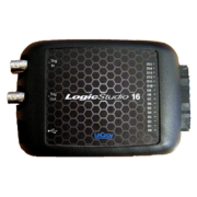
The LeCroy LogicStudio is a USB-based, 16-channel logic analyzer with 1GHz samplerate.
When all 16 channels are enabled, the maximum samplerate is limited to at most 500MHz. Either the lower eight or the upper eight channels may be disabled for an increased samplerate of up to 1GHz. The device offers a continuous acquisition mode where all inputs are sampled at a frequency of 1kHz. Its internal protocol decoder supports UART, I2C and SPI.
See LeCroy LogicStudio/Info for more details (such as lsusb -v output) about the device.
Hardware
- FPGA: Xilinx Spartan-6 XC6SLX16
- USB interface: Cypress CY7C68013A
- Crystal (FX2LP): 24.000MHz
- Crystal (FPGA): Unknown, xpress0?
Photos
Protocol
Trigger capabilities
The device has both standard logic triggers as well as triggers that operate on data produced by its internal protocol decoder. There are two logic trigger blocks A and B which can optionally be combined in the following ways:
- A AND B
- A OR B
- A THEN B
Each logic trigger block offers the following match criteria:
- Rising edge
- Falling edge
- Any edge
- Level 0 (including pulse width)
- Level 1 (ditto)
- Qualified edge triggers (trigger on rising/falling/any edge while another signal is high/low).
Multiple edge triggers in the same block are OR'd, while multiple level triggers in the same block are AND'ed. Each trigger block can further be configured with a number of times that the trigger criteria need to match before the trigger fires.
Internals
The device initially shows up as VID:PID 0x5ff:0xa001 on the USB bus. It then requires a firmware upload to its FX2LP chip, after which the original USB device disappears and a new one shows up, with VID:PID 0x5ff:0xa002.
The bitstreams for the FPGA come in two versions: one which enables all 16 channels, and one which only enables either the bottom 8 or the top 8 channels. If the first bitstream is uploaded, the maximum allowed sample rate is 500MHz. If the second bitstream is uploaded, the device can sample at up to 1GHz. In the latter case, a separate command controls whether the lower or the upper channels are enabled.
Samples are stored in the device's 40 KB memory. That memory block is used as a ringbuffer; samples are continuously written to it (thus overwriting old data if necessary) until the user-programmed trigger fires and the requested number of post-trigger samples have been acquired. At that point, you may retrieve the ringbuffer's contents from the device.
USB endpoints
- Endpoint 1 is used by the device to send acquisition status messages to the host.
- Endpoint 6 is used to upload the FPGA bitstream.
- Endpoint 2 is used to retrieve the device's samplebuffer.
Vendor requests are used to read or write control registers.
See LeCroy LogicStudio/Info for an lsusb -v.
Firmware revisions
As of October 2015, the latest released LeCroy LogicStudio software ships with FPGA bitstreams that are 464196 bytes and have the following hashes:
- md5(lecroy-logicstudio16-16.bitstream) = 1ab904704def72f18543d9d7aa929002
- md5(lecroy-logicstudio16-8.bitstream) = 5763c67cb762c85c8b1d09dc1f239acb
The FX2LP firmware is 4250 bytes:
- md5(lecroy-logicstudio16-fx2lp.fw) = 1638e2a5ef211c10f48405c1c16a057f


