Difference between revisions of "RadioShack 22-812"
m |
|||
| (20 intermediate revisions by 3 users not shown) | |||
| Line 1: | Line 1: | ||
[[File: | {{Infobox multimeter | ||
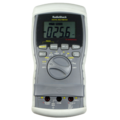
| image = [[File:radioshack_22_812_front.png|180px]] | |||
| name = RadioShack 22-812 | |||
| status = supported | |||
| source_code_dir = serial-dmm | |||
| counts = 4000 | |||
| categories = CAT II (600V) | |||
| connectivity = RS232 (standard DB9 connector) | |||
| measurements = voltage, temperature, current, resistance, capacitance, continuity, diode, logic, frequency, hFE, duty cycle, pulse width | |||
| features = autorange, data hold, min/max, dBmW (600Ω) | |||
| website = [https://www.radioshack.com/search/softwareResults.jsp?kw=22-812 radioshack.com] | |||
}} | |||
The | The '''RadioShack 22-812''' is a 4000 counts, CAT II (600V) handheld digital multimeter with RS-232 connectivity. | ||
It is no longer sold under this part number, and for a while, it appeared to have been discontinued. RadioShack does sell a visually identical multimeter, the [https://www.radioshack.com/product/index.jsp?productId=12988573 RadioShack 22-039]. It is not yet clear if the 22-039 is the same device as the 22-812. | |||
== Hardware == | == Hardware == | ||
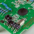
The | The microcontroller is an unidentifiable plastic blob. | ||
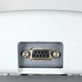
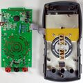
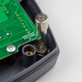
This devices has a standard DB-9 connector at the top, and does not require a special adapter cable. The RS-232 transmitter is optically insulated from the rest of the device. The transmitter uses a separate PCB, integrated into the multimeter's housing. The RS-232 module is powered from the serial port. | This devices has a standard DB-9 connector at the top, and does not require a special adapter cable. The RS-232 transmitter is optically insulated from the rest of the device. The transmitter uses a separate PCB, integrated into the multimeter's housing. The RS-232 module is powered from the serial port. | ||
| Line 12: | Line 25: | ||
<gallery> | <gallery> | ||
File:radioshack_22_812_front. | File:radioshack_22_812_front.png|<small>Mugshot</small> | ||
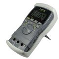
File:radioshack_22_812_angle.jpg|<small>Device, angle</small> | File:radioshack_22_812_angle.jpg|<small>Device, angle</small> | ||
File:radioshack_22_812_interface.jpg|<small>RS-232 connector</small> | File:radioshack_22_812_interface.jpg|<small>RS-232 connector</small> | ||
File:Radioshack_22_812_nocover_front.jpg|<small>Holster removed, front</small> | |||
File:Radioshack_22_812_nocover_front.jpg|<small> | File:Radioshack_22_812_nocover_back.jpg|<small>Holster removed, back</small> | ||
File:Radioshack_22_812_nocover_back.jpg|<small> | |||
File:Radioshack_22_812_batt.jpg|<small>Battery location</small> | File:Radioshack_22_812_batt.jpg|<small>Battery location</small> | ||
File:Radioshack_22_812_inside.jpg|<small>Opened up</small> | File:Radioshack_22_812_inside.jpg|<small>Opened up</small> | ||
File:Radioshack_22_812_pcb_removed.jpg|<small>PCB removed</small> | File:Radioshack_22_812_pcb_removed.jpg|<small>PCB removed</small> | ||
File:Radioshack_22_812_pcb_front.jpg|<small>PCB, front</small> | File:Radioshack_22_812_pcb_front.jpg|<small>PCB, front</small> | ||
File:Radioshack_22_812_pcb_back.jpg|<small>PCB, back</small> | File:Radioshack_22_812_pcb_back.jpg|<small>PCB, back</small> | ||
File:Radioshack_22_812_button pcb.jpg|<small> Buttons PCB</small> | File:Radioshack_22_812_button pcb.jpg|<small> Buttons PCB</small> | ||
File:Radioshack_22_812_transmitter.jpg|<small>RS-232 module</small> | File:Radioshack_22_812_transmitter.jpg|<small>RS-232 module</small> | ||
File:Radioshack_22_812_transmitte_module.jpg|<small>RS-232 transmitter</small> | File:Radioshack_22_812_transmitte_module.jpg|<small>RS-232 transmitter</small> | ||
File:Radioshack_22_812_transmitter_top.jpg|<small>RS-232 PCB, top</small> | File:Radioshack_22_812_transmitter_top.jpg|<small>RS-232 PCB, top</small> | ||
File:Radioshack_22_812_transmitter_back.jpg|<small>RS-232 PCB, bottom</small> | File:Radioshack_22_812_transmitter_back.jpg|<small>RS-232 PCB, bottom</small> | ||
File:Radioshack_22_812_terminal.jpg|<small>Banana sockets connecting to PCB</small> | File:Radioshack_22_812_terminal.jpg|<small>Banana sockets connecting to PCB</small> | ||
File:Radioshack_22_812_fuse holder.jpg|<small>Spare fuse</small> | File:Radioshack_22_812_fuse holder.jpg|<small>Spare fuse</small> | ||
File:Radioshack_22_812_chip.jpg|<small> | File:Radioshack_22_812_chip.jpg|<small>Multimeter IC</small> | ||
File:Radioshack_22_812_calibration.jpg|<small>Calibration pots</small> | File:Radioshack_22_812_calibration.jpg|<small>Calibration pots</small> | ||
</gallery> | </gallery> | ||
| Line 42: | Line 49: | ||
The device periodically sends 9-byte packets at 4800 baud, 8n1. | The device periodically sends 9-byte packets at 4800 baud, 8n1. | ||
The packet includes a mode indicator, payload and checksum. | The packet includes a mode indicator, payload and checksum. The payload is a 1-1 mapping of the LCD segments. | ||
=== Packet structure === | === Packet structure === | ||
{| border="0 | |||
{| border="0" style="font-size: smaller" class="alternategrey sigroktable" | |||
|- | |- | ||
! style="width: 3em;" | Byte | ! style="width: 3em;" | Byte | ||
| Line 65: | Line 73: | ||
| Hz | | Hz | ||
| Ohms | | Ohms | ||
| | | k | ||
| M | | M | ||
| F | | F | ||
| Line 146: | Line 154: | ||
=== Segment lettering === | === Segment lettering === | ||
{{7seg|A|F|B|G|E|C|D}} | |||
=== Mode byte === | === Mode byte === | ||
{| border="0 | {| border="0" style="font-size: smaller" class="alternategrey sigroktable" | ||
|- | |- | ||
! style="width: | ! style="width: 2em;" | Value | ||
! | ! Meaning | ||
|- | |- | ||
| Line 271: | Line 271: | ||
== Resources == | == Resources == | ||
* [http://code.google.com/p/rs22812/ rs22812.py project page] (Python interface to | * [http://code.google.com/p/rs22812/ rs22812.py project page] (Python interface to RadioShack 22-812 DMM) | ||
* [http://www.radioshack.com/graphics/uc/rsk/Support/ProductManuals/2200812A_PM_EN.pdf | * [http://www.radioshack.com/graphics/uc/rsk/Support/ProductManuals/2200812A_PM_EN.pdf RadioShack 22-812 user manual] | ||
[[Category:Device]] | [[Category:Device]] | ||
[[Category:Multimeter]] | [[Category:Multimeter]] | ||
[[Category:Supported]] | |||
Latest revision as of 04:32, 15 December 2012
 | |
| Status | supported |
|---|---|
| Source code | serial-dmm |
| Counts | 4000 |
| IEC 61010-1 | CAT II (600V) |
| Connectivity | RS232 (standard DB9 connector) |
| Measurements | voltage, temperature, current, resistance, capacitance, continuity, diode, logic, frequency, hFE, duty cycle, pulse width |
| Features | autorange, data hold, min/max, dBmW (600Ω) |
| Website | radioshack.com |
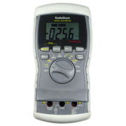
The RadioShack 22-812 is a 4000 counts, CAT II (600V) handheld digital multimeter with RS-232 connectivity.
It is no longer sold under this part number, and for a while, it appeared to have been discontinued. RadioShack does sell a visually identical multimeter, the RadioShack 22-039. It is not yet clear if the 22-039 is the same device as the 22-812.
Hardware
The microcontroller is an unidentifiable plastic blob.
This devices has a standard DB-9 connector at the top, and does not require a special adapter cable. The RS-232 transmitter is optically insulated from the rest of the device. The transmitter uses a separate PCB, integrated into the multimeter's housing. The RS-232 module is powered from the serial port.
Photos
Protocol
The device periodically sends 9-byte packets at 4800 baud, 8n1. The packet includes a mode indicator, payload and checksum. The payload is a 1-1 mapping of the LCD segments.
Packet structure
| Byte | 7 | 6 | 5 | 4 | 3 | 2 | 1 | 0 |
|---|---|---|---|---|---|---|---|---|
| 0 | Mode | |||||||
| 1 | Hz | Ohms | k | M | F | A | V | m |
| 2 | u | n | dBm | s | % | hFE | REL | MIN |
| 3 | 4D | 4C | 4G | 4B | DP3 | 4E | 4F | 4A |
| 4 | 3D | 3C | 3G | 3B | DP2 | 3E | 3F | 3A |
| 5 | 2D | 2C | 2G | 2B | DP1 | 2E | 2F | 2A |
| 6 | 1D | 1C | 1G | 1B | MAX | 1E | 1F | 1A |
| 7 | Beep | Diode | Bat | Hold | - | ~ | RS232 | Auto |
| 8 | Checksum | |||||||
Segment lettering
| A | ||
| F | B | |
| G | ||
| E | C | |
| D |
Mode byte
| Value | Meaning |
|---|---|
| 0 | DC V |
| 1 | AC V |
| 2 | DC uA |
| 3 | DC mA |
| 4 | DC A |
| 5 | AC uA |
| 6 | AC mA |
| 7 | AC A |
| 8 | Ohm |
| 9 | Capacitance |
| 10 | Hz (dial set to Hz) |
| 11 | Hz (dial set to DCV) |
| 12 | Hz (dial set to mA/A) |
| 13 | Duty cycle (dial set to Hz) |
| 14 | Duty cycle (dial set to DCV) |
| 15 | Duty cycle (dial set to mA/A) |
| 16 | Pulse width (dial set to Hz) |
| 17 | Pulse width (dial set to DCV) |
| 18 | Pulse width (dial set to mA/A) |
| 19 | Diode |
| 20 | Continuity (beep) |
| 21 | hFE |
| 22 | LOGIC |
| 23 | dBm |
| 24 | (Unknown) |
| 25 | Temp |
Resources
- rs22812.py project page (Python interface to RadioShack 22-812 DMM)
- RadioShack 22-812 user manual
