Difference between revisions of "Ideofy LA-08"
Uwe Hermann (talk | contribs) |
Uwe Hermann (talk | contribs) m |
||
| (6 intermediate revisions by 2 users not shown) | |||
| Line 1: | Line 1: | ||
{{Infobox logic analyzer | |||
| image = [[File:Ideofy_la_08.png|180px]] | |||
| name = Ideofy LA-08 | |||
| status = planned | |||
| source_code_dir = | |||
| channels = 8 | |||
| samplerate = 96MHz@2ch (or 60MHz@4ch, or 30MHz@8ch) | |||
| samplerate_state = ? | |||
| triggers = low, high, rising, falling, either | |||
| voltages = -0.7V — +16V | |||
| threshold = Fixed: VIH=2.0V, VIL=0.8V | |||
| memory = 100K~50Mpoints/channel | |||
| compression = ? | |||
| website = [http://www.ideofy.com/la-08_en ideofy.com] | |||
}} | |||
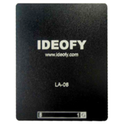
The '''Ideofy LA-08''' is a USB-based, 8-channel logic analyzer with a max. samplerate of 96MHz@2ch (or 60MHz@4ch, or 30MHz@8ch). | |||
See [[Ideofy LA-08/Info]] for more details (such as '''lsusb -vvv''' output) about the device. | See [[Ideofy LA-08/Info]] for more details (such as '''lsusb -vvv''' output) about the device. | ||
| Line 13: | Line 29: | ||
== Photos == | == Photos == | ||
<gallery> | |||
File:Ideofy la-08 mugshot.jpg|<small>Device, front</small> | |||
</gallery> | |||
== Protocol == | == Protocol == | ||
| Line 129: | Line 147: | ||
The ''0xa9'' byte is ''0x99'' sometimes. | The ''0xa9'' byte is ''0x99'' sometimes. | ||
== Resources == | |||
TODO. | |||
[[Category:Device]] | |||
[[Category:Logic analyzer]] | |||
[[Category:Planned]] | |||
Latest revision as of 08:10, 27 April 2013
 | |
| Status | planned |
|---|---|
| Channels | 8 |
| Samplerate | 96MHz@2ch (or 60MHz@4ch, or 30MHz@8ch) |
| Samplerate (state) | ? |
| Triggers | low, high, rising, falling, either |
| Min/max voltage | -0.7V — +16V |
| Threshold voltage | Fixed: VIH=2.0V, VIL=0.8V |
| Memory | 100K~50Mpoints/channel |
| Compression | ? |
| Website | ideofy.com |
The Ideofy LA-08 is a USB-based, 8-channel logic analyzer with a max. samplerate of 96MHz@2ch (or 60MHz@4ch, or 30MHz@8ch).
See Ideofy LA-08/Info for more details (such as lsusb -vvv output) about the device.
Hardware
- CMOS EEPROM-based programmable logic device (CPLD): Altera EPM3032A TC44-10N, MAX 3000A family (datasheet)
- USB high-speed USB peripheral controller: Cypress CY7C68013A-56LFXC (FX2) (datasheet)
- 2K I2C EEPROM: Microchip 24LC02B (datasheet)
- 600mA low-dropout voltage regulator: iDESYN iD9302 (datasheet)
- 24MHz crystal: TXC 24.0
Photos
Protocol
Firmware upload
The usual mechanism for uploading firmware to Cypress FX2 chips is used.
Query info / serial number (?)
A control transfer (direction: device->host, type: vendor-specific, request: 0xc2, value: 0x0000, index: 0x0000, length: 0x0020).
The 0x20 (32) bytes received contain the device's serial number as printed on the box (7 ASCII characters, can contain letters and digits), and some other, unknown info.
Example:
0x00 0x00 0x00 0x00 0x00 0x00 0x00 0x00 0x00 0x00 0x00 0x00 0x00 0x00 0x00 0x00
0x00 0x00 0x00 0x00 0x00 0x00 0x00 0x00 0x00 0x00 0x00 0x00 0x00 0x00 0x00 0x00
Note: Only the serial number location is marked, not all bytes are 0x00!
Starting an acquisition
To start an acquisition with a certain samplerate, a control transfer (direction: host->device, type: vendor-specific, request: 0xb6, with certain "value" and "index" entries, length: 0x0000) is sent to the device.
Samplerates
| Samplerate | Value | Index |
|---|---|---|
| 100kHz | 0x0006 | 0x9695 |
| 200kHz | 0x0000 | 0x9595 |
| 500kHz | 0x0000 | 0x3b3b |
| 1MHz | 0x0000 | 0x1d1d |
| 2MHz | 0x0000 | 0x0e0e |
| 5MHz | 0x0000 | 0x0505 |
| 10MHz | 0x0000 | 0x0202 |
| 15MHz | 0x0000 | 0x0101 |
| 24MHz | 0x0008 | 0x0101 |
| 30MHz | 0x0003 | 0x0101 |
Getting samples
The vendor software retrieves the samples in 0x4000 (16kB) chunks via bulk transfers (endpoint address: 0x86, i.e. endpoint 6).
Sample format
The probes (on the device housing) are numbered 1-8. They seem to have internal pull-ups, i.e. if you don't connect them to the target, their value will be high (1).
- 8 probes: Bit 7 is the value of probe 8, bit 0 is the value of probe 1.
- 4 probes: Bit 3 is the value of probe 4, bit 0 is the value of probe 1. Bits[7:4] are probes 4..1 respectively.
- 2 probes: Bit 1 is the value of probe 2, bit 0 is the value of probe 1. Bits[7:6], bits[5:4], and bits[3:2] are probes 2..1 respectively.
Triggers
Implemented purely in software, it seems.
Stopping acquisition / reset (?)
After an acquisition the vendor software sends a control transfer (direction: host->device, type: vendor-specific, request: 0xb7, value: 0x0000, index: 0x0000, length: 0x0000) to the device.
Status (?)
A control transfer (direction: device->host, type: vendor-specific, request: 0xb5, value: 0x0000, index: 0x0000, length: 0x0040) is also sent after an acquisition.
This retrieves 0x40 (64) bytes from the device, which probably represent status values or the like.
Example:
0x00 0x01 0x00 0x00 0xff 0xPP 0xQQ 0xRR 0x55 0x55 0x02 0x00 0x86 0xa9 0x00 0x00
0x00 0x00 0x00 0x00 0x00 0x00 0x00 0x00 0x00 0x00 0x00 0x00 0x00 0x00 0x00 0x00
0x00 0x00 0x00 0x00 0x00 0x00 0x00 0x00 0x00 0x00 0x00 0x00 0x00 0x00 0x00 0x00
0x00 0x00 0x00 0x00 0x00 0x00 0x00 0x00 0x00 0x00 0x00 0x00 0x00 0x00 0x00 0x00
The "0xPP 0xQQ 0xRR" bytes seem to differ upon most sample runs (as do some of the other bytes). The last 48 bytes seem to be 0x00 always.
Byte 1 seems to have 0x00 and 0x01 as possible values.
Bytes 0x55 0x55 and byte 0x86 seem to not change usually.
The 0x02 byte is 0x03 sometimes.
The 0xa9 byte is 0x99 sometimes.
Resources
TODO.
