Difference between revisions of "Velleman PS3005D"
Jump to navigation
Jump to search
Uwe Hermann (talk | contribs) (Move protocol info to main page as on all other hardware pages.) |
Uwe Hermann (talk | contribs) m (→Resources) |
||
| Line 130: | Line 130: | ||
* [http://www.velleman.eu/downloads/2/ps3005d_cdrom.zip Driver CD-ROM] | * [http://www.velleman.eu/downloads/2/ps3005d_cdrom.zip Driver CD-ROM] | ||
* [http://antanas.veiverys.com/velleman-ps3005d-remote-control-commands/ Remote control commands] | * [http://antanas.veiverys.com/velleman-ps3005d-remote-control-commands/ Remote control commands] | ||
* [http://www.eevblog.com/forum/testgear/power-supply-ps3005d-ka3005d-rs232-protocol/ eevblog.com: Power Supply PS3005D / KA3005D RS232 protocol] | |||
[[Category:Device]] | [[Category:Device]] | ||
[[Category:Power supply]] | [[Category:Power supply]] | ||
[[Category:Planned]] | [[Category:Planned]] | ||
Revision as of 16:51, 21 June 2014
 | |
| Status | planned |
|---|---|
| Channels | 1 |
| Voltage/current (CH1) | 0-30V / 0-5A |
| Connectivity | USB, RS232 |
| Features | programmable presets, over voltage protection, over current protection, output on/off |
| Website | velleman.eu |
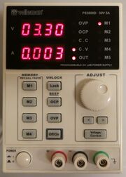
The Velleman PS3005D is a 1-channel programmable power supply (0-30V/0-5A) with both USB and RS232 connectivity.
It is probably a rebadged Korad KA3005P.
See Velleman PS3005D/Info for more details (such as lsusb -v output) about the device.
Hardware
TODO.
Photos
Protocol
The protocol is serial or serial-over-USB, 9600 8N1, (almost fully) ASCII based. No line termination, CRC or checksum characters are used. The PC sends a request string which is then responded by the power supply.
During a PC connection, the front control buttons and the scrollwheel are blocked.
| Request | Example output | Remarks |
|---|---|---|
| *IDN? | VELLEMANPS3005DV2.0
KORADKA3005PV2.0 |
Request identification from device |
| STATUS? | (byte) | Request the actual status. The output is a single byte with the actual status encoded in bits. At least the Velleman PS3005D V2.0 is a bit buggy here. The only reliable bits are: 0x40 (Output mode: 1:on, 0:off), 0x20 (OVP and/or OCP mode: 1:on, 0:off) and 0x01 (CV/CC mode: 1:CV, 0:CC) |
| VSET1? | 12.34 | Request the voltage as set by the user. |
| VSET1:12.34 | (none) | Set the maximum output voltage. |
| VOUT1? | 12.34 | Request the actual voltage output. |
| ISET1? | 0.125 | Request the current as set by the user. |
| ISET1:0.125 | (none) | Set the maximum output current. |
| IOUT1? | 0.125 | Request the actual output current. |
| OUT1 | (none) | Enable the power output. |
| OUT0 | (none) | Disable the power output. |
| OVP1 | (none) | Enable the "Over Voltage Protection", the PS will switch off the output when the voltage raises above the actual level. |
| OVP0 | (none) | Disable the "Over Voltage Protection". |
| OCP1 | (none) | Enable the "Over Current Protection", the PS will switch off the output when the current raises above the actual level. |
| OCP0 | (none) | Disable the "Over Current Protection". |
Remarks:
- The digit 1 in the V... and I... requests indicates the values are meant for channel one. In future (or "higher"?) models this may be two for a second channel and so on.
- Voltage ("00.00" to "31.00" V) and current ("0.000" to "5.100" A) output values have a fixed length with fixed dot position. The values won't become negative.


