Difference between revisions of "User talk:Mrnuke"
| Line 82: | Line 82: | ||
<gallery> | <gallery> | ||
File:Mrnuke_bc_85xa_signal_at_ir_led_tx.png|<small>Signal at IR LED with vendor software attempting to connect. (AC coupled)</small> | File:Mrnuke_bc_85xa_signal_at_ir_led_tx.png|<small>Signal at IR LED with vendor software attempting to connect. (AC coupled)</small> | ||
<gallery> | </gallery> | ||
=== Photos === | === Photos === | ||
Revision as of 02:07, 11 December 2012
BM857 PC interface cable
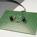
I'm trying to build a PC interface cable for my Brymen BM857. I have used Radioshack 276-142 IR diode and photo-transistor set, and a PL2303 USB to serial converter.
If you have a real cable you'd like to donate, hop on to #sigrok and contact me.
Info
This is an experimental homebrew design. It does NOT work. The manufacturer's cable contains a PIC microcontroller that communicates with the PC, and multimeter. The data sent through the serial port is not what the DMM receives/sends. Any straight cable will not work.
It is unclear if the IR protocol is a simple UART, or is pulse-width based, or if it uses any other encoding.
Schematic
Photos
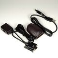
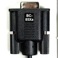
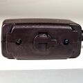
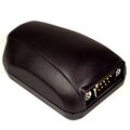
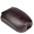
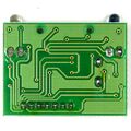
Brymen BC-85Xa interface cable
This is the official interface cable sold by Brymen. It works with the BM857a and BM859a, but does not work with thw non-a models.
Reverse engineering the cable
It is clear at this point that the protocol on the RS-232 side is not the same as the protocol used on the IR side. This raises an interesting question: Can the protocol be reversed-engineered and implemented as a simple UART? If the IR encoding is a simple UART, then it is feasible. A "brymen-dmm-raw" driver could provide users with a quick way to put together a circuit and communicate with their Brymen.
Connector pinout
| RS232 pin | Conductor pin
|
|---|---|
| 1 - DCD | NC |
| 2 - Rx | 7 - Red |
| 3 - Tx | 6 - Yellow |
| 4 - DTR | 5 - Green |
| 5 - GND | 1 - Blue |
| 6 - DSR | 4 - Gray |
| 7 - RTS | 3 - White |
| 8 - CTS | 2 - Black |
| 9 - RI | NC |
Infrared Signal
I thought it would be interested to see how the signal at the IR LED looks like. Since I didn't have an oscilloscope or logic analyzer available at the time, I used my sound card to record the signal. The AC coupling of the sound card makes the signal look funny, but the edges are clearly visible.
The first pulse is about 9ms long, while the second pulse is 10ms long. The two pulses are spaced 265ms apart. It looks as if the communication may be pulse-width based. Without having a cable/multimeter set that works, it is impossible to say more.
Photos
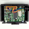
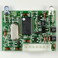
These are from the Extech SW810a kit. The components are all manufactured by Brymen, and carry the Brymen part numbers.
