Difference between revisions of "Metrix MX56C"
Uwe Hermann (talk | contribs) (Metrix MX56C is supported now.) |
Tsaitgaist (talk | contribs) (replace user manual dead link) |
||
| (2 intermediate revisions by one other user not shown) | |||
| Line 7: | Line 7: | ||
| categories = CAT III (600V) | | categories = CAT III (600V) | ||
| connectivity = RS232 | | connectivity = RS232 | ||
| measurements = voltage, resistance, diode, continuity, capacitance, frequency, duty cycle, current | | measurements = voltage, resistance, diode, continuity, capacitance, frequency, duty cycle, pulse count, current, power, gain | ||
| features = autorange, hold, relative, bargraph, backlight, true-rms | | features = autorange, hold, relative, bargraph, backlight, true-rms, AC+DC | ||
| website = [http://web.archive.org/web/20031103154311/http://www.chauvin-arnoux.com/produit/Famille_detail.asp?idFam=855&idPole=1 chauvin-arnoux.com] | | website = [http://web.archive.org/web/20031103154311/http://www.chauvin-arnoux.com/produit/Famille_detail.asp?idFam=855&idPole=1 chauvin-arnoux.com] | ||
}} | }} | ||
| Line 18: | Line 18: | ||
== Hardware == | == Hardware == | ||
The vendor specifically announces the high IP rating, and the advanced safety features. | |||
The labelling suggests that "ASYC" stands for "Advanced Safety Concept". | |||
Some models "lock" the probes, such that special action needs to be taken before they can get unplugged. | |||
The battery and fuse compartment only can get accessed after the probes were removed. | |||
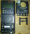
The tilt stand at the back of the device can get removed, and then be used as a tool to open the front cover. | |||
The locations for the tool during this activity are marked. | |||
Removing the front cover allows access to the battery and the fuses. | |||
The tool can be used to further open the device and remove the back cover as well, to access the PCB inside the meter. | |||
But that activity is not suggested, and is not needed for regular use. | |||
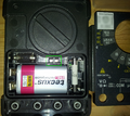
The location of the IR LEDs is rather unusual -- right underneath the range selector, within the battery compartment. | |||
This is especially annoying as the meter has a high IP rating, which results in extra covers for improved isolation from environmental influences. | |||
A special kit is sold for serial communication, which includes an alternative cover that replaces the originally shipped cover around the range selector. | |||
(No further hardware details here, neither teardown images -- see the EEVblog link in the resources section. | |||
Images there show a DMM chip labelled "ITT" and "METRIX DMM5", and a flyer for the serial communication kit. | |||
User "free_electron" provides background on the ITT corporation.) | |||
== Photos == | == Photos == | ||
<gallery> | |||
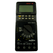
File:mx56c-front-holster.png|<small>front view, with holster</small> | |||
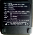
File:mx56c-back-instructions.png|<small>back view, button and power-on instructions</small> | |||
File:mx56c-display-asyc-ip67.png|<small>display, bargraph, ASYC(R) II label, IP67 rating</small> | |||
File:mx56c-batt-compart-ir-location.png|<small>battery compartment, IR LED location</small> | |||
File:mx56c-batt-compart-covers.png|<small>battery compartment, model name, rubber cover, tilt stand</small> | |||
</gallery> | |||
== Protocol == | == Protocol == | ||
=== Dumb mode (PRINT button) === | |||
When the user presses the PRINT button, the meter periodically sends measurement data via IR. | |||
Holding the PRINT button allows adjustment of the interval (seconds resolution, up to 10 hours). | |||
The PRINT button needs to get pressed again each time the function selection is changed. | |||
Data is communicated via UART frames in 8n1 format at 2400bps. | |||
All communicated bytes are in the ASCII range. | |||
Each packet consists of 16 bytes which includes the CR terminator. | |||
The packet contains a (signed) number value, then scale factor and unit for the measurement, and optional flags. | |||
The absence of separators between the packet's fields makes case _sensitive_ parsing essential, | |||
case insensitive operation would become ambiguous and would even break successful operation of the driver. | |||
$ '''stty -F /dev/ttyUSB0 2400''' | |||
$ '''hexdump -Cv < /dev/ttyUSB0''' | |||
00000000 2d 30 2e 30 30 30 34 20 56 64 63 20 20 20 20 0d |-0.0004 Vdc .| | |||
00000010 20 30 2e 30 30 30 37 20 56 64 63 20 20 20 20 0d | 0.0007 Vdc .| | |||
00000020 20 30 2e 30 30 30 30 20 56 64 63 20 20 20 20 0d | 0.0000 Vdc .| | |||
00000030 20 30 2e 30 30 30 30 20 56 64 63 20 20 20 20 0d | 0.0000 Vdc .| | |||
00000040 20 30 2e 30 30 30 30 20 56 64 63 20 20 20 20 0d | 0.0000 Vdc .| | |||
00000050 20 30 2e 30 30 30 33 20 56 64 63 20 20 20 20 0d | 0.0003 Vdc .| | |||
00000060 20 34 39 2e 36 39 33 4d 6f 68 6d 20 20 20 20 0d | 49.693Mohm .| | |||
00000070 20 34 39 2e 39 38 37 4d 6f 68 6d 20 20 20 20 0d | 49.987Mohm .| | |||
00000080 20 34 39 2e 39 38 35 4d 6f 68 6d 20 20 20 20 0d | 49.985Mohm .| | |||
00000090 20 20 30 30 2e 30 30 6e 46 20 20 20 20 20 20 0d | 00.00nF .| | |||
000000a0 20 20 30 30 2e 30 30 6e 46 20 20 20 20 20 20 0d | 00.00nF .| | |||
000000b0 20 20 30 30 2e 30 30 6e 46 20 20 20 20 20 20 0d | 00.00nF .| | |||
The sigrok driver currently only implements support for this PRINT mode. | |||
=== Smart mode ("RS 232 mode") === | |||
When the PK button is pressed at power-on, "RS 232 mode" gets enabled. | |||
All operation still is controlled by the meter's range selector and buttons, but UART communication via IR becomes bidirectional. | |||
The peer can query the current mode and state (and needs to reflect on that in its subsequent communication, the available documentation explicitly warns about sending commands that don't match the meter's capabilities or mode!). | |||
The peer can request the previous or a next measurement, which might result in higher update rates compared to the PRINT mode. | |||
Requests and responses in this mode are variable width (model dependent!), and "mostly ASCII" with occasional use of control characters. | |||
While packets are of variable length, there are no record separators which would allow for synchronization to the data stream, or recognition of frame borders independently from (assumed) presence of a specific model. | |||
Maybe a sequence of ESC and ENQ/ACK might help when synchronization was lost. | |||
See the ASYC2 related PDF in the resources section for details. | |||
The sigrok driver currently lacks support for this mode. | |||
== Resources == | == Resources == | ||
| Line 32: | Line 97: | ||
* [http://web.archive.org/web/20060319202158/http://www.chauvin-arnoux.com/produit/famille_liste.asp?idRub=1529&idpole=1 Vendor software] | * [http://web.archive.org/web/20060319202158/http://www.chauvin-arnoux.com/produit/famille_liste.asp?idRub=1529&idpole=1 Vendor software] | ||
* http://www.eevblog.com/forum/testgear/metrix-mx56c-bk-precision-5390-multimeter-teardown/ | * http://www.eevblog.com/forum/testgear/metrix-mx56c-bk-precision-5390-multimeter-teardown/ | ||
* http://www.chauvin-arnoux.us/pdfs_aemc/user-manuals/MX56_EN.pdf | * [https://web.archive.org/web/20160313124153/http://www.chauvin-arnoux.us/pdfs_aemc/user-manuals/MX56_EN.pdf User Manual] | ||
* http://www.snesometel.com.tn/images/PDF/NF-SX-ASYC2.pdf Interface description with protocol. | * http://www.snesometel.com.tn/images/PDF/NF-SX-ASYC2.pdf Interface description with protocol. | ||
Latest revision as of 05:27, 19 December 2024
 | |
| Status | supported |
|---|---|
| Source code | serial-dmm |
| Counts | 50000 |
| IEC 61010-1 | CAT III (600V) |
| Connectivity | RS232 |
| Measurements | voltage, resistance, diode, continuity, capacitance, frequency, duty cycle, pulse count, current, power, gain |
| Features | autorange, hold, relative, bargraph, backlight, true-rms, AC+DC |
| Website | chauvin-arnoux.com |
The Metrix MX56C is a 50000 counts, CAT III (600V) handheld digital multimeter with RS232 connectivity.
The same device was also sold as BK Precision 5390.
Hardware
The vendor specifically announces the high IP rating, and the advanced safety features. The labelling suggests that "ASYC" stands for "Advanced Safety Concept". Some models "lock" the probes, such that special action needs to be taken before they can get unplugged. The battery and fuse compartment only can get accessed after the probes were removed.
The tilt stand at the back of the device can get removed, and then be used as a tool to open the front cover. The locations for the tool during this activity are marked. Removing the front cover allows access to the battery and the fuses. The tool can be used to further open the device and remove the back cover as well, to access the PCB inside the meter. But that activity is not suggested, and is not needed for regular use.
The location of the IR LEDs is rather unusual -- right underneath the range selector, within the battery compartment. This is especially annoying as the meter has a high IP rating, which results in extra covers for improved isolation from environmental influences. A special kit is sold for serial communication, which includes an alternative cover that replaces the originally shipped cover around the range selector.
(No further hardware details here, neither teardown images -- see the EEVblog link in the resources section. Images there show a DMM chip labelled "ITT" and "METRIX DMM5", and a flyer for the serial communication kit. User "free_electron" provides background on the ITT corporation.)
Photos
Protocol
Dumb mode (PRINT button)
When the user presses the PRINT button, the meter periodically sends measurement data via IR. Holding the PRINT button allows adjustment of the interval (seconds resolution, up to 10 hours). The PRINT button needs to get pressed again each time the function selection is changed.
Data is communicated via UART frames in 8n1 format at 2400bps. All communicated bytes are in the ASCII range. Each packet consists of 16 bytes which includes the CR terminator. The packet contains a (signed) number value, then scale factor and unit for the measurement, and optional flags. The absence of separators between the packet's fields makes case _sensitive_ parsing essential, case insensitive operation would become ambiguous and would even break successful operation of the driver.
 $ stty -F /dev/ttyUSB0 2400
 $ hexdump -Cv < /dev/ttyUSB0
 00000000  2d 30 2e 30 30 30 34 20  56 64 63 20 20 20 20 0d  |-0.0004 Vdc    .|
 00000010  20 30 2e 30 30 30 37 20  56 64 63 20 20 20 20 0d  | 0.0007 Vdc    .|
 00000020  20 30 2e 30 30 30 30 20  56 64 63 20 20 20 20 0d  | 0.0000 Vdc    .|
 00000030  20 30 2e 30 30 30 30 20  56 64 63 20 20 20 20 0d  | 0.0000 Vdc    .|
 00000040  20 30 2e 30 30 30 30 20  56 64 63 20 20 20 20 0d  | 0.0000 Vdc    .|
 00000050  20 30 2e 30 30 30 33 20  56 64 63 20 20 20 20 0d  | 0.0003 Vdc    .|
 00000060  20 34 39 2e 36 39 33 4d  6f 68 6d 20 20 20 20 0d  | 49.693Mohm    .|
 00000070  20 34 39 2e 39 38 37 4d  6f 68 6d 20 20 20 20 0d  | 49.987Mohm    .|
 00000080  20 34 39 2e 39 38 35 4d  6f 68 6d 20 20 20 20 0d  | 49.985Mohm    .|
 00000090  20 20 30 30 2e 30 30 6e  46 20 20 20 20 20 20 0d  |  00.00nF      .|
 000000a0  20 20 30 30 2e 30 30 6e  46 20 20 20 20 20 20 0d  |  00.00nF      .|
 000000b0  20 20 30 30 2e 30 30 6e  46 20 20 20 20 20 20 0d  |  00.00nF      .|
The sigrok driver currently only implements support for this PRINT mode.
Smart mode ("RS 232 mode")
When the PK button is pressed at power-on, "RS 232 mode" gets enabled. All operation still is controlled by the meter's range selector and buttons, but UART communication via IR becomes bidirectional. The peer can query the current mode and state (and needs to reflect on that in its subsequent communication, the available documentation explicitly warns about sending commands that don't match the meter's capabilities or mode!). The peer can request the previous or a next measurement, which might result in higher update rates compared to the PRINT mode.
Requests and responses in this mode are variable width (model dependent!), and "mostly ASCII" with occasional use of control characters. While packets are of variable length, there are no record separators which would allow for synchronization to the data stream, or recognition of frame borders independently from (assumed) presence of a specific model. Maybe a sequence of ESC and ENQ/ACK might help when synchronization was lost. See the ASYC2 related PDF in the resources section for details.
The sigrok driver currently lacks support for this mode.


