Difference between revisions of "Voltcraft VC-96"
Jump to navigation
Jump to search
Uwe Hermann (talk | contribs) m |
Uwe Hermann (talk | contribs) (Mugshot.) |
||
| (2 intermediate revisions by the same user not shown) | |||
| Line 1: | Line 1: | ||
{{Infobox multimeter | {{Infobox multimeter | ||
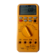
| image = | | image = [[File:Voltcraft vc96 mugshot.png|180px]] | ||
| name = Voltcraft VC-96 | | name = Voltcraft VC-96 | ||
| status = supported | | status = supported | ||
| Line 17: | Line 17: | ||
== Photos == | == Photos == | ||
<gallery> | |||
File:Voltcraft vc96 top.jpg|<small>Device, top</small> | |||
File:Voltcraft vc96 back.jpg|<small>Device, bottom</small> | |||
File:Voltcraft vc96 left with adapter.jpg|<small>Device, left</small> | |||
File:Voltcraft vc96 pcb front.jpg|<small>PCB, top</small> | |||
File:Voltcraft vc96 pcb back.jpg|<small>PCB, bottom</small> | |||
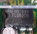
File:Voltcraft vc96 main chip.jpg|<small>Main chip</small> | |||
File:Voltcraft vc96 front rectifier under shunt.jpg|<small>Rectifier</small> | |||
File:Voltcraft vc96 chip top right.jpg|<small>Chip, top</small> | |||
File:Voltcraft vc96 chip left.jpg|<small>Chip, left</small> | |||
File:Voltcraft vc96 chip led center.jpg|<small>Chip, LED</small> | |||
File:Voltcraft vc96 chip front top left.jpg|<small>Chip</small> | |||
File:Voltcraft vc96 chip front bottom right.jpg|<small>Chip</small> | |||
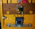
File:Voltcraft vc96 usb modification.jpg|<small>USB modification</small> | |||
File:Voltcraft vc96 usb micro instead subd25.jpg|<small>Micro-USB instead of DB-25</small> | |||
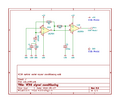
File:Voltcraft vc96 usb modification schematics.png|<small>Modification schematics</small> | |||
</gallery> | |||
== Protocol == | == Protocol == | ||
The device sends always (without request) about 4 telegrams per second with 1200 baud, 8N2 over the LED through the case. | |||
The location of the LED is marked on the back (the little circle above the screw). | |||
The converter originally has a RS232 25pin sub-d and needs an 9VDC power supply, but can be modified with a little TTL serial to USB board. | |||
The handling remains the same except using /dev/ttyUSBx instead of /dev/ttySx. | |||
Example packets: | |||
<small> | |||
ACV 0.0 V\r\n | |||
ACV 0.00 V\r\n | |||
DCV 00uV\r\n | |||
DCV 0.0 V\r\n | |||
DCV- 0.1mV\r\n | |||
OHM OL M<0xEA>\r\n | |||
DIO OL V\r\n | |||
BEP OL K<0xEA>\r\n | |||
DIO OL V\r\n | |||
DCA 00uA\r\n | |||
hfe 0.0 \r\n | |||
DCA 02uA\r\n | |||
DCA 0.0mA\r\n | |||
DCA 00mA\r\n | |||
ACA 761mA\r\n | |||
ACA 0.0mA\r\n | |||
</small> | |||
The device does not send packets in CAP and in FREQ mode. | |||
== Resources == | == Resources == | ||
Latest revision as of 13:50, 15 December 2019
 | |
| Status | supported |
|---|---|
| Source code | serial-dmm |
| Counts | 4000 |
| Connectivity | RS232 |
| Measurements | voltage, capacitance, continuity, diode, frequency, current, |
| Features | autorange, hold, relative, min-max, hfe, bargraph |
| Website | kappenberg.com |
The Voltcraft VC-96 is an 4000 counts handheld, digital multimeter with RS232 (D-sub, DB-25 connector) connectivity.
Hardware
Photos
Protocol
The device sends always (without request) about 4 telegrams per second with 1200 baud, 8N2 over the LED through the case.
The location of the LED is marked on the back (the little circle above the screw).
The converter originally has a RS232 25pin sub-d and needs an 9VDC power supply, but can be modified with a little TTL serial to USB board.
The handling remains the same except using /dev/ttyUSBx instead of /dev/ttySx.
Example packets:
ACV   0.0 V\r\n
ACV  0.00 V\r\n
DCV    00uV\r\n
DCV   0.0 V\r\n
DCV-  0.1mV\r\n
OHM   OL M<0xEA>\r\n
DIO   OL  V\r\n
BEP   OL K<0xEA>\r\n
DIO   OL  V\r\n
DCA    00uA\r\n
hfe   0.0  \r\n
DCA    02uA\r\n
DCA   0.0mA\r\n
DCA    00mA\r\n
ACA   761mA\r\n
ACA   0.0mA\r\n
The device does not send packets in CAP and in FREQ mode.


