Difference between revisions of "Braintechnology USB-LPS"

From sigrok
Jump to navigation Jump to search
m
m
 
(6 intermediate revisions by 3 users not shown)
Line 1: Line 1:
[[File:Braintechnology usb lps.jpg|thumb|right|Braintechnology USB-LPS]]
{{Infobox logic analyzer
| image            = [[File:Braintechnology usb lps.png|180px]]
| name            = Braintechnology USB-LPS
| status          = supported
| source_code_dir  = fx2lafw
| channels        = 8/16
| samplerate      = 24MHz
| samplerate_state = —
| triggers        = none (SW-only)
| voltages        = -0.5V — 5.25V
| threshold        = Fixed: VIH=2.0V—5.25V, VIL=-0.5V—0.8V
| memory          = none
| compression      = none
| website          = [http://www.braintechnology.de/webshop/catalog/product_info.php?&products_id=105 braintechnology.de]
}}


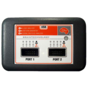
The [http://www.braintechnology.de/webshop/catalog/product_info.php?&products_id=105 Braintechnology USB-LPS] is a Cypress FX2 based 16-channel, 24MHz, USB-based logic analyzer and signal/pattern generator.
The '''Braintechnology USB-LPS''' is a Cypress FX2 based 16-channel, 24MHz, USB-based logic analyzer and signal/pattern generator.


See [[Braintechnology USB-LPS/Info]] for some more details (such as '''lsusb -vvv''' output) on the device.
In sigrok, the open-source [[fx2lafw]] firmware and driver is used for this device.


In sigrok, the open-source [[fx2lafw]] firmware and driver is used for this device.
See [[Braintechnology USB-LPS/Info]] for some more details (such as '''lsusb -v''' output) on the device.


== Hardware ==
== Hardware ==


* Cypress CY7C68013A-56PVXC (FX2)
* '''Main chip:''' Cypress CY7C68013A-56PVXC (FX2LP)
* Atmel ATTiny13-20SU
* '''I²C EEPROM''': Atmel ATtiny13-20SU
* LD33 (3.3V voltage regulator)
* '''3.3V voltage regulator''': LD33
* 24MHz crystal
* '''Crystal''': 24MHz


== Photos ==
== Photos ==


<gallery>
<gallery>
File:Braintechnology usb lps.jpg|<small>Braintechnology USB-LPS</small>
File:Braintechnology usb lps.jpg|<small>Device, front</small>
File:Braintechnology usb lps pcb front.jpg|<small>Braintechnology USB-LPS, PCB front</small>
File:Braintechnology usb lps pcb front.jpg|<small>PCB, front</small>
File:Braintechnology usb lps pcb front details.jpg|<small>Braintechnology USB-LPS, PCB front details</small>
File:Braintechnology usb lps pcb front details.jpg|<small>PCB, front, details</small>
File:Braintechnology usb lps pcb back.jpg|<small>Braintechnology USB-LPS, PCB back</small>
File:Braintechnology usb lps pcb back.jpg|<small>PCB, back</small>
</gallery>
</gallery>


== Protocol ==
== Protocol ==


=== Firmware upload ===
Since we use the open-source [[fx2lafw]] firmware for this device, we don't need to know the protocol.
 
The FX2 firmware (3072 bytes in size) is uploaded before every sampling run. Certain bytes in the firmware differ depending on the selected sampling rate.
 
=== Starting a sampling run ===
 
The host seems to send: 0x00 0x01 0x00 0x00 0x00
 
=== Stopping a sampling run ===
 
The host seems to send: 0x00 0x00 0x00 0x00 0x00
 
=== Sample rates ===
 
<table><tr valign="top"><td>
 
'''Sampling with 8 probes:'''
 
{| border="0" style="font-size: smaller"
|- bgcolor="#6699ff"
!Samplerate
!Divider
!Other byte
|- bgcolor="#eeeeee"
| 24 MHz
| 0x01
| 0xee
|- bgcolor="#dddddd"
| 16 MHz
| 0x02
| 0xee
|- bgcolor="#eeeeee"
| 15 MHz
| 0x01
| 0xae
|- bgcolor="#dddddd"
| 12 MHz
| 0x03
| 0xee
|- bgcolor="#eeeeee"
| 10 MHz
| 0x02
| 0xae
|- bgcolor="#dddddd"
| 8 MHz
| 0x05
| 0xee
|- bgcolor="#eeeeee"
| 6 MHz
| 0x07
| 0xee
|- bgcolor="#dddddd"
| 5 MHz
| 0x05
| 0xae
|- bgcolor="#eeeeee"
| 4 MHz
| 0x0b
| 0xee
|- bgcolor="#dddddd"
| 3 MHz
| 0x0f
| 0xee
|- bgcolor="#eeeeee"
| 2.5 MHz
| 0x0b
| 0xae
|- bgcolor="#dddddd"
| 2 MHz
| 0x17
| 0xee
|- bgcolor="#eeeeee"
| 1.5 MHz
| 0x1f
| 0xee
|- bgcolor="#dddddd"
| 1 MHz
| 0x2f
| 0xee
|- bgcolor="#eeeeee"
| 800 kHz
| 0x3b
| 0xee
|- bgcolor="#dddddd"
| 750 kHz
| 0x3f
| 0xee
|- bgcolor="#eeeeee"
| 600 kHz
| 0x4f
| 0xee
|- bgcolor="#dddddd"
| 500 kHz
| 0x5f
| 0xee
|- bgcolor="#eeeeee"
| 400 kHz
| 0x77
| 0xee
|- bgcolor="#dddddd"
| 300 kHz
| 0x9f
| 0xee
|- bgcolor="#eeeeee"
| 250 kHz
| 0xbf
| 0xee
|- bgcolor="#dddddd"
| 200 kHz
| 0xef
| 0xee
|- bgcolor="#eeeeee"
| 150 kHz
| 0xc7
| 0xae
|- bgcolor="#dddddd"
| 120 kHz
| 0xf9
| 0xae
|}
 
</td><td>
 
'''Sampling with 16 probes:'''
 
{| border="0" style="font-size: smaller"
|- bgcolor="#6699ff"
!Samplerate
!Divider
!Other byte
|- bgcolor="#eeeeee"
| &nbsp;
|
|
|- bgcolor="#dddddd"
| &nbsp;
|
|
|- bgcolor="#eeeeee"
| &nbsp;
|
|
|- bgcolor="#dddddd"
| 12 MHz
| 0x03
| 0xee
|- bgcolor="#eeeeee"
| 10 MHz
| 0x02
| 0xae
|- bgcolor="#dddddd"
| 8 MHz
| 0x05
| 0xee
|- bgcolor="#eeeeee"
| 6 MHz
| 0x07
| 0xee
|- bgcolor="#dddddd"
| 5 MHz
| 0x05
| 0xae
|- bgcolor="#eeeeee"
| 4 MHz
| 0x0b
| 0xee
|- bgcolor="#dddddd"
| 3 MHz
| 0x0f
| 0xee
|- bgcolor="#eeeeee"
| 2.5 MHz
| 0x0b
| 0xae
|- bgcolor="#dddddd"
| 2 MHz
| 0x17
| 0xee
|- bgcolor="#eeeeee"
| 1.5 MHz
| 0x1f
| 0xee
|- bgcolor="#dddddd"
| 1 MHz
| 0x2f
| 0xee
|- bgcolor="#eeeeee"
| 800 kHz
| 0x3b
| 0xee
|- bgcolor="#dddddd"
| 750 kHz
| 0x3f
| 0xee
|- bgcolor="#eeeeee"
| 600 kHz
| 0x4f
| 0xee
|- bgcolor="#dddddd"
| 500 kHz
| 0x5f
| 0xee
|- bgcolor="#eeeeee"
| 400 kHz
| 0x77
| 0xee
|- bgcolor="#dddddd"
| 300 kHz
| 0x9f
| 0xee
|- bgcolor="#eeeeee"
| 250 kHz
| 0xbf
| 0xee
|- bgcolor="#dddddd"
| 200 kHz
| 0xef
| 0xee
|- bgcolor="#eeeeee"
| 150 kHz
| 0xc7
| 0xae
|- bgcolor="#dddddd"
| 120 kHz
| 0xf9
| 0xae
|}
 
</td></tr></table>
 
The byte values for sampling with 8 or 16 probes are thus identical, the only difference is that the sampling rates 24/16/15MHz are not available when 16 probes are used.
 
=== Sample format ===
 
* 8 bit sampling: Every sample is a byte, bit 0 is the value of probe 0, bit 7 is the value of probe 7.
* 16 bit sampling: Every sample consists of two bytes.
** First byte: Bit 0 is the value of probe 0, bit 7 is the value of probe 7.
** Second byte: Bit 0 is the value of probe 8, bit 7 is the value of probe 15.
 
=== Buffer size ===
 
Not relevant to the protocol, happens purely in software, on the PC side (by sending the "stop acquisition" command at the correct point in time).
 
The original software allows setting a buffer size to 1-2433 MB, in 1MB steps. This is simply the amount of data streamed from the device to the PC (there is no device-internal buffer/memory).
 
=== Pre-Trigger value ===
 
Not relevant to the protocol, happens purely in software, on the PC side.
 
The original software has a pretrigger setting (a scrollbar); it's unclear whether this is an absolute value or a percentage or something else.
 
=== Trigger settings ===
 
Not relevant to the protocol, happens purely in software, on the PC side.


The original software allows setting per-probe triggers (4 levels deep). At each level the trigger for that probe can be low, high, or dont-care.
However, for those interested in this, see our old [[Braintechnology_USB-LPS/Info#Vendor_USB_protocol|vendor protocol docs]].


== Resources ==
== Resources ==


TODO.
* [http://www.braintechnology.de/downstat18/download.php?file=lps_doc.pdf Manual]
* [http://www.braintechnology.de/downstat18/download.php?file=lpssetup10723.exe Vendor software]
* [http://www.braintechnology.de/downstat18/download.php?file=lpsdriver_32_64bit.zip Driver]


[[Category:Device]]
[[Category:Device]]
[[Category:Logic analyzer]]
[[Category:Logic analyzer]]
[[Category:Supported]]

Latest revision as of 18:05, 28 May 2017

Braintechnology USB-LPS
Braintechnology usb lps.png
Status supported
Source code fx2lafw
Channels 8/16
Samplerate 24MHz
Samplerate (state)
Triggers none (SW-only)
Min/max voltage -0.5V — 5.25V
Threshold voltage Fixed: VIH=2.0V—5.25V, VIL=-0.5V—0.8V
Memory none
Compression none
Website braintechnology.de

The Braintechnology USB-LPS is a Cypress FX2 based 16-channel, 24MHz, USB-based logic analyzer and signal/pattern generator.

In sigrok, the open-source fx2lafw firmware and driver is used for this device.

See Braintechnology USB-LPS/Info for some more details (such as lsusb -v output) on the device.

Hardware

  • Main chip: Cypress CY7C68013A-56PVXC (FX2LP)
  • I²C EEPROM: Atmel ATtiny13-20SU
  • 3.3V voltage regulator: LD33
  • Crystal: 24MHz

Photos

Protocol

Since we use the open-source fx2lafw firmware for this device, we don't need to know the protocol.

However, for those interested in this, see our old vendor protocol docs.

Resources