Difference between revisions of "Protocol decoder:Esp8266"
Jump to navigation
Jump to search
| Line 1: | Line 1: | ||
=== Modules === | === Modules === | ||
| Line 25: | Line 5: | ||
* ESP-01 | * ESP-01 | ||
<blockquote> | <blockquote> | ||
Connector: 2x4pin male 2.54mm header | |||
{|style="border-width: 0px" | |||
| style="width: 300px" | | |||
{| border="0" style="margin-top: 0px; font-size: smaller; text-align: center" class="alternategrey sigroktable" | |||
|+ Connector pinout | |||
|- | |||
{| border="0" style="font-size: smaller; text-align: center" class="alternategrey sigroktable" | ! Function | ||
|- | ! Pin | ||
! style="border-left:2px solid gray" | Pin | |||
! Function | |||
|- | |||
| <div>{{ESP8266EXpin|26}}</div> | |||
|- | | 1 | ||
| style="border-left:2px solid gray" | 2 | |||
| GND | |||
|- | |||
| <div>{{ESP8266EXpin|7}}</div> | |||
|- | | 3 | ||
| style="border-left:2px solid gray" | 4 | |||
| <div>{{ESP8266EXpin|14}}</div> | |||
|- | |||
| <div>{{ESP8266EXpin|32}}</div> | |||
|- | | 5 | ||
| style="border-left:2px solid gray" | 6 | |||
| <div>{{ESP8266EXpin|15}}</div> | |||
|- | |||
| VCC | |||
|- | | 7 | ||
| style="border-left:2px solid gray" | 8 | |||
| <div>{{ESP8266EXpin|25}}</div> | |||
|} | |||
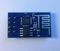
<small>(Note: The PCB has two square pads at the pin header, so it's not clear which one should be pin number 1. The table above assumes that the module is oriented as shown in the picture from the top, with the antenna on the right side, pin 1 is then in the top left corner and pin 8 next to the SPI flash chip.)</small> | |||
| style="vertical-align: top" | | |||
<gallery> | |||
File:ESP-01.jpg|<small>ESP-01, top</small> | |||
File:ESP-01_flash.jpg|<small>[http://www.gigadevice.com/product/detail/5/119.html GigaDevice GD25Q40B] 4Mbit SPI flash</small> | |||
</gallery> | |||
|} | |} | ||
</blockquote> | </blockquote> | ||
| Line 153: | Line 137: | ||
|} | |} | ||
</blockquote> | </blockquote> | ||
Revision as of 02:54, 6 November 2014
Modules
Various online marketplaces sell modules containing the ESP8266 (and a few assisting components) that comes preprogrammed with a TCP/IP stack that can be controlled via RS232 commands.
- ESP-01
Connector: 2x4pin male 2.54mm header
Connector pinout Function Pin Pin Function 1 2 GND 3 4 5 6 VCC 7 8 (Note: The PCB has two square pads at the pin header, so it's not clear which one should be pin number 1. The table above assumes that the module is oriented as shown in the picture from the top, with the antenna on the right side, pin 1 is then in the top left corner and pin 8 next to the SPI flash chip.)
GigaDevice GD25Q40B 4Mbit SPI flash
- ESP-04
Connectors: 7 pin castellated holes on both sides (2mm distance)
Pinout of left connector Pin Function 1 VCC 2 3 4 5 6 7
Pinout of right connector Pin Function 1 2 3 4 5 6 n.c. 7 GND
- ESP-05
Connectors: 1x5pin pads (2.54mm distance), U.FL antenna connector
Connector pinout Pin Function 1 2 GND 3 4 5 VCC

