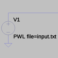
File format:pwl
 A voltage source using values from a PWL file. | |
| Name | Piecewise linear function |
|---|---|
| Status | unsupported |
| Common extension(s) | .txt |
| ASCII format | yes |
| Compression | none |
pwl is a file format that can be used to define the signal of voltage/current sources in a SPICE simulation.
Format
The file consists of multiple time/value pairs. The individual values are separated by whitespace, therefore all values can be in one long line, or on multiple lines (much more convenient). The time values have to be in increasing order. SI prefixes are supported for both the time and the value.
The content in the file is then accessed with the PWL file=… statement from the simulation.
Time intervals
Please note that very often, simulation is done in irregular time intervals, that is, for more complex moments of a simulation, a SPICE simulator will save a lot of time/value pairs, while during less complex moments, it will only save a few. Depending on the simulation, you can have time differences ranging from seconds to nanoseconds, sometimes in the same file. This could prove unconvenient if another module of sigrok needs a file that has regular timesteps (for example, .wav audio, some signal generators, etc.). So there will need to be a method of "regularizing" the timesteps. This is done most easily by either linear interpolation or bandwidth-limited interpolation, which is used by Tek's ArbExpress, for example.
To understand interpolation, imagine the following: you are given a set of points in a Cartesian plot, f(t,X). You want to guess the X value between two of those points, so you use a formula, you give that formula the t (time) value of the X you want to find, the coordinates of the point before t and the coordinates of the point after t and the formula gives you an X value. That can be programmed into a function.
You also have to write a function that can find the points before and after t, the function could be sort of random access or sequential access, doesn't matter, in our application we will be doing sequential access, so that's up to the person who implements it.
We mentioned two types of interpolation, here are some details:
- Linear interpolation is very easy, only a simple equation, and could be the place to start development. The wikipedia article on linear interpolation is more than enough to understand it. Wikipedia
- Bandwidth limited interpolation is more specialized, but implementations can be found in audio applications, where often you need to convert between sample rates. An audacity plugin may have an implementation, and perhaps in a high level language. Anyway, here is a paper on bandwidth limited interpolation: link
PWL in different SPICE implementations
LTspice
Observations
- A space (0x20) or different newline indicators (CR (0x0D), LF (0x0A) and CR+LF) can be used to separate the times/values.
- When editing the properties of a voltage/current source in the LTspice editor and choosing the PWL file, the "Open File" dialog uses "ASCII File (*.txt)" as the default filter (but the simulation can use every other file extension too).
Screenshots
Ngspice
- Ngspice user's manual
- Blogpost by Henrik Forstén that involves reading audio data from a file using Ngspice (by using a Python script to get the data into the correct format, link to source on github at the bottom of the page).
Observations
- Ngspice's PWL source can't read from a file, however there is a model called filesource instead (section 12.2.8 in the user's manual):
- The input file is read line by line. (The actual implementation of the module uses fgets() to read the individual lines.)
- The characters '#' and ';' start a comment, the rest of the line after them is ignored.
- A line can contain two or more values, the first is the timestamp, the other values are the outputs of the model.
- Ngspice also has a digital source called d_source (section 12.4.21 in the user's manual):
- Again, the file is read line by line using fgets().
- The character '*' starts a comment.
- A line contains a timestamp an one or more digital values.
- A digital value consists of two characters, the first defines the actual value (0/1/undefined) and the second the "strength" of the state (strong/resistive/hi-impedance/undetermined), as documented in section 12.5.1 "Digital Node Type" of the user's guide.