Getting started with a logic analyzer
After installing sigrok you can immediately start using sigrok through different frontends. Currently, those are PulseView, sigrok-cli and sigrok-meter.
Capturing Signals
The sigrok suite needs some kind of hardware to interface to the signals you want to examine. While multimeters are certainly supported, we found that most people are currently using logic analyzers based on the Cypress FX2 microcontroller. With fx2lafw, sigrok's open source runtime firmware, any device containing an FX2 can become a powerful streaming logic analyzer.
A variety of compatible low cost chinese made logic analyzer products are available for as little as $10. These can easily be found by searching for 24MHz Logic Analyzer. There are also base-board Cypress FX2 boards such as the Lcsoft Mini Board, which can usually be found by searching for Cypress FX2 Board or similar.
In addition, a good set of quality probe hooks is recommended. The E-Z-Hook XKM series hooks are highly recommended, and are available from resellers such as DigiKey.
Sigrok Signal Capture
For this example we are going to perform an analysis on a signal captured from a Dallas DS1307 I²C Real-Time Clock chip, which measures the time of day.
The sigrok-dumps repository contains a pre-made capture of DS1307 signalling.
We now start up the PulseView sigrok GUI, and open the file sigrok-dumps/i2c/rts_dallas_ds1307/rtc_ds1307_200khz.sr. We can see the captured signal, which features a conversation between a microcontroller and the DS1307, where the microcontroller repeatedly sets and queries the time of day:
Sigrok Signal Decoding
Now we have the captured signal we can make use of sigrok's support for signal decoding. It allows signal decoding through the use of Python-language Protocol Decoder scripts. This makes it very quick and easy to build powerful decoders for all forms of digital signalling. We hope to be able to build a vibrant decoder library that will contain a large selection of supported chips and protocols.
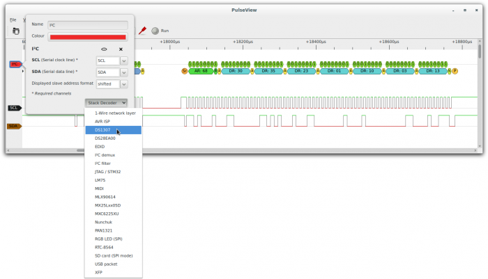
Because we know that this is I²C signalling, we can add an I²C decoder from the Decoders menu:
Normally we would need to associate the logic probes with the logic analyzer inputs, but in this case, because the probes are already labelled SCL and SDA, PulseView can do this automatically. We can now see that sigrok has decoded the I²C messages and displays them with a blob diagram.
This is already very useful, and a massive improvement over counting out pulses on an oscilloscope screen. However, sigrok allows us to go one step further with the use of so-called stacked decoders.
To add a stacked decoder we go to the Stack Decoder menu, and select the DS1307 decoder.
With the stacked decoder added, we can now see that sigrok has decoded the meaning of the I²C commands, so that we don't need to bother searching the reference manual. In this view, we can see that the I²C packet was a command to read the date and time, which was 10.03.2013 23:35:30.
Advanced analysis with sigrok-cli
sigrok-cli is a command line front-end for sigrok. Signal analysis via the command line is a powerful method of working, particularly when used with UNIX pipes. Downstream programs and scripts can be used to search, filter, condition or format the data in whatever way is desired.
This blog post demonstrates how to extract a .WAV file from I²S digital sound signalling, for example.
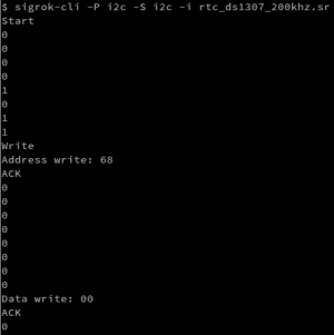
In the case of our DS1307 example, we can also load the file with sigrok-cli. The data is displayed as bits by default:
Or we can display the signal as ASCII art:
Now we can decode the I²C packet data, just like in PulseView:
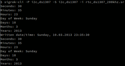
And as before we can decode the DS1307 commands:
Additionally, it is possible to run analyzers with a live capture such as in this example utilizing the fx2lafw driver and monitoring one side of a SPI transaction:
sigrok-cli --config samplerate=1M --driver=fx2lafw --continuous -P spi:mosi=1:clk=3:cs=4
When combined with tools such as grep, egrep, sed, perl, python, and many others, all kinds of powerful analysis becomes possible.


