Unused files
Jump to navigation
Jump to search
The following files exist but are not embedded in any page. Please note that other web sites may link to a file with a direct URL, and so may still be listed here despite being in active use.
Showing below up to 50 results in range #51 to #100.
View (previous 50 | next 50) (20 | 50 | 100 | 250 | 500)
- Lcsoft cy7c68013a pcb top.jpg 1,024 × 768; 711 KB
- Lcsoft cy7c68013a pcb bottom.jpg 1,024 × 768; 632 KB
- Pv 24xx byte write.png 1,366 × 720; 56 KB
- Pv 24xx page write.png 1,366 × 720; 87 KB
- Pv midi.png 733 × 510; 31 KB
- U1732b top.JPG 3,072 × 2,304; 3.07 MB
- DVM4100 Inside.jpg 1,418 × 3,264; 1.2 MB
- Dds120 front.jpg 2,112 × 2,106; 534 KB
- Sainsmart dds120 front 6.jpg 6,016 × 4,000; 5.28 MB
- Crystal 24MHz.jpg 6,016 × 4,000; 2.87 MB
- Ht-usbee-axpro.png 360 × 186; 113 KB
- P3330 device back.jpg 2,448 × 3,264; 1.88 MB
- P3330 device front.jpg 3,264 × 2,448; 2.01 MB
- P3330 front holster.jpg 2,448 × 3,264; 2.12 MB
- P3330 lcd backlight.jpg 2,448 × 3,264; 1.33 MB
- P3330 lcd indicator.jpg 2,448 × 3,264; 1.95 MB
- P3330 pcb dmmchip.jpg 2,448 × 3,264; 2.33 MB
- P3330 pcb dmmchip closeup.jpg 2,448 × 3,264; 2.24 MB
- P3330 pcb input.jpg 2,448 × 3,264; 2.16 MB
- P3330 pcb twoboard.jpg 3,264 × 2,448; 1.72 MB
- P3330 range labels.jpg 2,448 × 3,264; 2.17 MB
- P3330 serial cables.jpg 3,264 × 2,448; 1.28 MB
- P2170 accessories.jpg 3,264 × 2,448; 2.25 MB
- P2170 device back.jpg 2,448 × 3,264; 1.24 MB
- P2170 device front.jpg 2,448 × 3,264; 1.32 MB
- P2170 lcd capacitance.jpg 2,448 × 3,264; 1.98 MB
- P2170 lcd resistance.jpg 2,448 × 3,264; 1.85 MB
- P2170 pcb bottom.jpg 2,448 × 3,264; 2.11 MB
- P2170 pcb top input.jpg 2,448 × 3,264; 2.13 MB
- P2170 pcb top lcrchip.jpg 2,448 × 3,264; 2.17 MB
- P2170 pcb top.jpg 2,448 × 3,264; 2.11 MB
- Fx2grok-tiny-0.1-kicad-schematics.svg 1,052 × 744; 346 KB
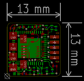
- Fx2grok-tiny-0.1-kicad-layout.png 511 × 491; 16 KB
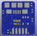
- Fx2grok-tiny-0.1-kicad-3d-top.png 627 × 605; 33 KB
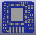
- Fx2grok-tiny-0.1-kicad-3d-bottom.png 627 × 605; 73 KB
- Fx2grok 0 1 stencil paste preparation.jpg 1,024 × 768; 270 KB
- Fx2grok 0 1 stencil paste applied.jpg 1,024 × 768; 271 KB
- Fx2grok 0 1 stencil.jpg 1,024 × 768; 276 KB
- Fx2grok 0 1 pcb under stencil.jpg 1,024 × 768; 250 KB
- Fx2grok 0 1 pcb top soldered.jpg 1,024 × 768; 188 KB
- Fx2grok 0 1 pcb top paste.jpg 1,024 × 768; 272 KB
- Fx2grok 0 1 pcb top.jpg 1,024 × 768; 269 KB
- Fx2grok 0 1 pcbs.jpg 1,024 × 768; 351 KB
- Fx2grok 0 1 pcb on masking tape.jpg 1,024 × 768; 278 KB
- Fx2grok 0 1 pcb bottom soldered.jpg 1,024 × 768; 226 KB
- Fx2grok 0 1 pcb bottom populated.jpg 1,024 × 768; 264 KB
- Fx2grok 0 1 pcb bottom paste.jpg 1,024 × 768; 264 KB
- Fx2grok 0 1 pcb bottom kapton tape.jpg 1,024 × 768; 260 KB
- Fx2grok 0 1 pcb bottom.jpg 1,024 × 768; 326 KB
- Fx2grok 0 1 pcb under stencil closeup.jpg 1,024 × 768; 440 KB


