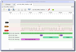
Protocol decoder:xy2-100
 | |
| Name | XY2-100(E) and XY2-200(E) interface decoder |
|---|---|
| Description | XY2-100(E) protocol used in laser applications |
| Status | supported |
| License | GPLv2+ |
| Source code | decoders/xy2-100 |
| Input | logic |
| Output | — |
| Probes | CLK, SYNC, DATA |
| Optional probes | STATUS |
| Options | none |
The xy2-100 protocol decoder can decode XY2-100-based protocols used in laser scanning applications.
Description
The most often encountered setups use common clock and sync signals with two pairs of data and status signals - one for the X and one for the Y axis. Sometimes, a Z axis is also present. All signals are transmitted differentially.
There are multiple variants of this protocol:
- XY2-100 is the base variant with a clock frequency of up to 2 MHz
- XY2-200 is XY2-100 with a clock frequency of up to 4 MHz
- XY2-100E and XY2-200E are enhanced variants, offering the possibility to send additional commands to the scanner and the user can influence the format of the status channel
The primary functionality of the protocol is submitting 16-bit signed integers to the scanner to control the galvanometer position. Presumably with the -E variants, the protocol also allows this to be extended to 18 bits, although this will render the parity bit pretty much useless. The reason is that the 18-bit mode is in part indicated by an inverted parity bit (odd parity) while the command mode uses the default even parity. This means that it's impossible to determine when a command mode transmission was corrupted as it'll just look like an 18-bit position transmission and vice versa. The PD emits a warning for this reason, just to make users aware.