Protocol decoder:esp8266
 | |
| Name | ESP8266 |
|---|---|
| Description | WiFi Serial Transceiver. |
| Status | stalled |
| License | GPLv2+ |
| Source code | decoders/ |
| Input | uart |
| Output | esp8266 |
| Probes | — |
| Optional probes | — |
The esp8266 protocol decoder supports the UART command protocol spoken by modules equipped with an ESP8266 WiFi transceiver chip.
Because of various problems with the UART commands (random lockups, no escaping of special characters, responses of multiple commands mixing up, ...), the work on this decoder has stopped. If you own such a chip, you are probably better off by directly reprogramming it's CPU, this article provides a good starting point.
Hardware
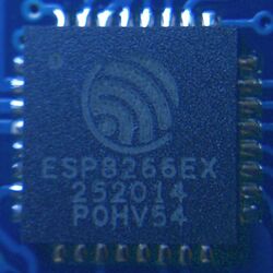
The ESP8266 chip contains an Xtensa LX106 CPU and a radio for IEEE 802.11b/g/n.
Modules
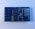
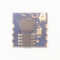
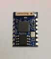
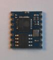
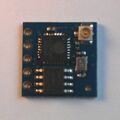
Various online marketplaces sell modules containing the ESP8266 (and a few assisting components) that comes preprogrammed with a TCP/IP stack that can be controlled with commands send via RS232. There seem to be eleven different types of modules around, called "ESP-01" to "ESP-11" (see this post).
- ESP-01
Connector: 2x4pin male 2.54mm header
Connector pinout Function Pin Pin Function 1 2 GND 3 4 5 6 VCC 7 8 (Note: The PCB has two square pads at the pin header, so it's not clear which one should be pin number 1. The table above assumes that the module is oriented as shown in the picture from the top, with the antenna on the right side, pin 1 is then in the top left corner and pin 8 next to the SPI flash chip.)
GigaDevice GD25Q40B 4Mbit SPI flash
- ESP-02
Connectors: 4 pin castellated holes on both sides (2.54 distance)
Pinout of left connector Pin Function 1 GND 2 3 4 VCC
Pinout of right connector Pin Function 1 2 3 4
- ESP-03
Connectors: 7 pin castellated holes on both sides (2mm distance)
Pinout of left connector Pin Function 1 VCC 2 3 4 5 6 7
Pinout of right connector Pin Function 1 2 3 4 5 6 n.c. 7 GND
- ESP-04
Connectors: 7 pin castellated holes on both sides (2mm distance), same pinout as ESP-03
- ESP-05
Connectors: 1x5pin pads (2.54mm distance), U.FL antenna connector
Connector pinout Pin Function 1 2 GND 3 4 5 VCC
