Difference between revisions of "IKALOGIC Scanalogic-2"
Marc Schink (talk | contribs) m (→Device status) |
Marc Schink (talk | contribs) (Fix acquisition example.) |
||
| Line 110: | Line 110: | ||
The following example starts an acquisition with a samplerate of 5MHz and with 2384 samples before and 17456 samples after the trigger occurs. The trigger is configured to channel 2 with a rising edge and is delayed for 20000ms. | The following example starts an acquisition with a samplerate of 5MHz and with 2384 samples before and 17456 samples after the trigger occurs. The trigger is configured to channel 2 with a rising edge and is delayed for 20000ms. | ||
0x01 0x00 0x2A 0x01 0x86 0x08 0x02 0x01 0x03 0x00 0x20 0x4E 0x00 0x00 0x00 | 0x01 0x00 0x2A 0x01 0x86 0x08 0x02 0x01 0x03 0x00 0x20 0x4E 0x00 0x00 0x00 0x00 | ||
0x00 0x00 0x00 0x00 0x00 0x00 0x00 0x00 0x00 ... | 0x00 0x00 0x00 0x00 0x00 0x00 0x00 0x00 0x00 ... | ||
Revision as of 21:20, 14 June 2013
 | |
| Status | supported |
|---|---|
| Source code | ikalogic-scanalogic2 |
| Channels | 4 |
| Samplerate | 20MHz |
| Samplerate (state) | — |
| Triggers | rising, falling, either |
| Min/max voltage | -0.7V — 5.5V |
| Threshold voltage | ? |
| Memory | 256ksamples/ch |
| Compression | none |
| Website | ikalogic.com |
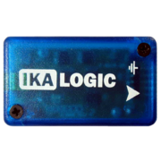
The Ikalogic SCANALOGIC-2 is a USB-based, 4-channel logic analyzer with up to 20MHz sampling rate.
See Ikalogic SCANALOGIC-2/Info for more details (such as lsusb -vvv output) about the device.
Hardware
- Atmel ATmega168 PA (datasheet)
- 2x Fairchild Semiconductor 74LCX125
- 4x Microchip 23K256I (datasheet)
- 20MHz crystal
Photos
Device built from DIY soldering kit, firmware version 1.2:
Another device, firmware version 1.3:
Protocol
In progress.
Starting an acquisition
An acquisition can be started by sending 128 bytes to the device, of which only the first 12 bytes (which are described below) have a meaning. All following bytes can have an arbitrary value. The device is capable to acquire up to 262128 samples whereas the vendor software limits it to 261888 samples. The number of pre- and post-trigger samples together must not exceed the sample limit of the device.
| Byte(s) | Value | Description |
|---|---|---|
| 0 | 0x01 | Command which indicates to start an acquisition. |
| 1 | 0x00 | This byte must always be 0x00. |
| 2-3 | Pre-trigger samples | Number of samples to acquire in multiples of 8 before the trigger occurs. |
| 4-5 | Post-trigger samples | Number of samples to acquire in multiples of 8 after the trigger occurs. |
| 6 | Samplerate | |
| 7 | Trigger type | |
| 8 | Trigger channel | |
| 9 | 0x00 | This byte must always be 0x00. |
| 10-11 | After trigger delay | Time that the trigger will be delayed in milliseconds. The trigger can be delayed from 0 to 65000ms. |
The following example starts an acquisition with a samplerate of 5MHz and with 2384 samples before and 17456 samples after the trigger occurs. The trigger is configured to channel 2 with a rising edge and is delayed for 20000ms.
0x01 0x00 0x2A 0x01 0x86 0x08 0x02 0x01  0x03 0x00 0x20 0x4E 0x00 0x00 0x00 0x00
0x00 0x00 0x00 0x00 0x00 0x00 0x00 0x00  0x00 ...
Device status
The device status can be obtained by requesting 128 bytes from the device. The first 2 bytes of the response (which are described below) have a meaning only. All following bytes can be ignored. Note that it might take a short time until a valid device status is received. In the meantime the last valid data of the device buffer will be received.
| Byte(s) | Value | Description |
|---|---|---|
| 0 | 0x05 | This byte indicates a valid device status. |
| 1 | Status | See the table below for a description of all possible status codes. |
All possible status codes are listed in the following table.
| Status | Description |
|---|---|
| 0x60 | Sample data is ready to receive. |
| 0x61 | Device is waiting for a trigger event. |
| 0x62 | Sampling in progress. |
| 0x63 | Device is ready. |


