Difference between revisions of "Protocol decoder:Iebus"
m (Move references to Resources) |
|||
| Line 31: | Line 31: | ||
== Protocol == | == Protocol == | ||
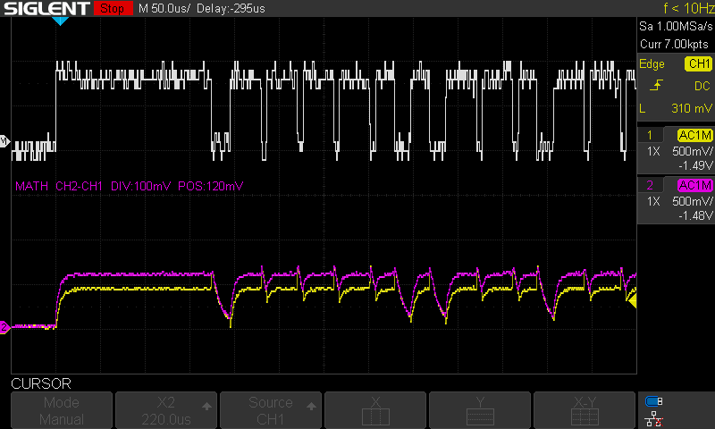
The scope captures below show an IEBus operating in Mode 2 which means that the time for each bit is 39µs. The example scope trace below provides an overview of the voltages and timings that with which the bus operates: | |||
The scope captures below show an IEBus operating in Mode 2 which means that the time for each bit is 39µs. | |||
The example scope trace below provides an overview of the voltages and timings that with which the bus operates: | |||
[[File:Iebus-mode2-frame.png]] | [[File:Iebus-mode2-frame.png]] | ||
| Line 59: | Line 51: | ||
== Resources == | == Resources == | ||
* | The protocol itself has been documented pretty extensively on Wikipedia as well as other more | ||
niche pages: | |||
* [https://en.wikipedia.org/wiki/IEBus Wikipedia] | |||
* [http://softservice.com.pl/corolla/avc/avclan.php Softservice] | |||
* [https://elinux.org/AVC-LAN eLinux] | |||
* [https://pop.fsck.pl/hardware/toyota-corolla.html] | |||
* [http://www.interfacebus.com/Design_Connector_IEbus.html] | |||
[[Category:Protocol decoder]] | [[Category:Protocol decoder]] | ||
[[Category:CAN]] | [[Category:CAN]] | ||
Revision as of 13:11, 7 June 2023
| Name | IEBus |
|---|---|
| Description | A multi-drop multi-master differential CAN-like bus |
| Status | 100% |
| License | GPLv3+ |
| Source code | decoders/ |
| Input | logic |
| Output | iebus |
| Probes | — |
| Optional probes | ? |
| Options | — |
The iebus protocol decoder handles decoding of the IEBus, a lower-level layer of the AVC-LAN protocol which is used in multimedia control applications in Toyota and other brand cars. It's connected with Python output to avclan which is a higher-level decoder handling the decoding of frame contents, identifying devices on the bus based on their addresses and functions and so on.
Hardware
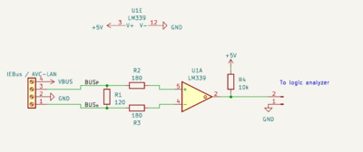
The protocol capture can be performed with a comparator circuit connected to 4 resistors:
Photos:
None
Protocol
The scope captures below show an IEBus operating in Mode 2 which means that the time for each bit is 39µs. The example scope trace below provides an overview of the voltages and timings that with which the bus operates:
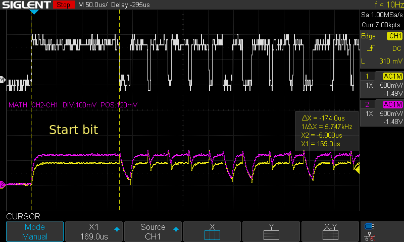
Each frame begins with a start bit:
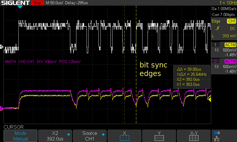
which is followed by a number of data bits where each bit can be synchronized by a raising edge, a synchronization period and a data period. This is highlighed in the trace below:
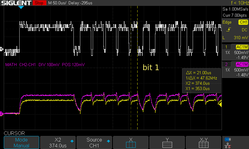
In practice the decoder implementation waits for the sync period to expire and then samples the bus to probe which bit is being transmitted. An alternative approach can be also used where a decoder can measure the pulse length between the rising synchronization edge and the falling edge before the next bit is being transmitted. The below traces provide a comparison between what happens on the bus when 0 and 1 are being transmitted:
Resources
The protocol itself has been documented pretty extensively on Wikipedia as well as other more niche pages:
