Difference between revisions of "SainSmart DDS140"
SamantazFox (talk | contribs) (→Hardware: Add some of the logic analyzer and signal generator components) |
SamantazFox (talk | contribs) (→Hardware: Fix error made in previous change: the two AD devices in SOIC8 are completely different chips) |
||
| Line 26: | Line 26: | ||
* Signal generator: | * Signal generator: | ||
** '''CMOS Single 8-Channel Analog Multiplexer/Demultiplexer''' [https://www.ti.com/product/CD4052B Texas Instruments CD4052B] ([https://www.ti.com/lit/ds/symlink/cd4052b.pdf datasheet]) | ** '''CMOS Single 8-Channel Analog Multiplexer/Demultiplexer''' [https://www.ti.com/product/CD4052B Texas Instruments CD4052B] ([https://www.ti.com/lit/ds/symlink/cd4052b.pdf datasheet]) | ||
** | ** '''90 MHz Variable Gain Amplifier''' [https://www.analog.com/en/products/ad603.html Analog Devices AD603AR] ([https://www.analog.com/media/en/technical-documentation/data-sheets/AD603.pdf datasheet]) | ||
** '''Dual Operational Amplifier''' [https://www.analog.com/en/products/ad826.html Analag Devices AD826] ([https://www.analog.com/media/en/technical-documentation/data-sheets/AD826.pdf datasheet]) | |||
== Photos - Oscillocope (main unit) == | == Photos - Oscillocope (main unit) == | ||
Latest revision as of 20:46, 26 September 2020
The SainSmart DDS140 is a USB-based, 2-channel oscilloscope with an analog bandwidth of 40MS/s and 200MS/s sampling rate.
Optionally, it also supports usage as signal generator or logic analyzer.
See SainSmart DDS140/Info for more details (such as lsusb -v output) about the device.
Hardware
- Main unit:
- USB: Cypress CY7C68013A-100AXC (FX2LP) (datasheet)
- 64-kbyte I²C EEPROM: Microchip 24LC64I (datasheet)
- Dual 8bit, 100MSPS ADC: MXTronix MXT2088 (datasheet)
- 5x CMOS differential 4-channel analog mux/demux with logic-level conversion: Texas Instruments CD4052BM (datasheet)
- CPLD: Altera MAX II EPM240T100CN (datasheet)
- 64K x 16 CMOS anyc SRAM (8ns): ISSI IS61LV6416-8TI (datasheet)
- Dual voltage comparator: TI LM393 (datasheet)
- 1A low-dropout voltage regulator (3.3V): Advanced Monolithic Systems AMS1117-3.3 (datasheet)
- Crystal: 24MHz (for Cypres FX2)
- Crystal: 80MHz (for Altera MAX II)
- Logic analyzer:
- Octal translating transceiver NXP (Nexperia) LVC4245A (datasheet)
- Signal generator:
- CMOS Single 8-Channel Analog Multiplexer/Demultiplexer Texas Instruments CD4052B (datasheet)
- 90 MHz Variable Gain Amplifier Analog Devices AD603AR (datasheet)
- Dual Operational Amplifier Analag Devices AD826 (datasheet)
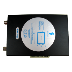
Photos - Oscillocope (main unit)
Photos - Signal generator extension
Photos - Logic analyzer extension
Protocol
The protocol used by this device is not based on anything else. It seems to be based on a raw data exchange using a WinUSB pipe.
Sending commands
The DDS140 uses a simple set of command codes (uint8_t, from 0 to 255) that may take arguments.
The host software uses an helper DLL to send theses commands to the device. In this DLL, two functions act as a wrapper around WinUsb_ControlTransfer():
- USBCtrlTransSimple() is used for simple commands, that does not take arguments
- USBCtrlTrans() is used for more complex commands, i.e that takes arguments
It has to be noted that both functions can return data.
The list of currently reversed command codes is available here:
- https://gitlab.com/SamantazFox/dds140-reverse-engineering/-/blob/master/program/Commands_summary.rst (main)
- https://github.com/SamantazFox/dds140-reverse-engineering/blob/master/program/Commands_summary.rst (mirror)
Getting the data back
the process that gets the data back from the device is not well understood yet. It seems that the helper DLL contains a wrapper function around WinUsb_ReadPipe() (for raw buffer read), plus a lot of pre-processing (via the DataPreDisposal() function) which is directly dependant of the GUI settings (graph zoom and position).
This has yet to be reversed.


