Difference between revisions of "Rigol VS5202D"

From sigrok
Jump to navigation Jump to search
(Added URL to Rigol Programming Guide found on ze interwebs)
 
(23 intermediate revisions by 7 users not shown)
Line 1: Line 1:
[[File:Rigol_VS5202D_Full.jpg|thumb|right|Rigol VS5000 series]]
[[File:Rigol_VS5202D.png|thumb|right|Rigol VS5202D]]


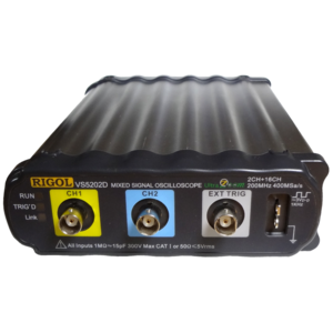
The [http://rigol.com/ Rigol VS5202D] is a 2 channel analog and 16 channel digital, 200 MHz, USB-based oscilloscope/logic analyzer.
The [http://rigol.com/ Rigol VS5202D] is a discontinued 2 channel analog and 16 channel digital, 200 MHz, USB- and Ethernet-based oscilloscope/logic analyzer.
 
The device is [http://int.rigol.com/prodserv/Discontinued%20products/ discontinued by Rigol], but you can find the basic specs e.g. [http://www.batronix.com/shop/oscilloscopes/Rigol-VS5202D.html here].


See [[Rigol VS5202D/Info]] for some more details (such as '''lsusb -vvv''' output) on the device.


More information will come in due time.
See [[Rigol VS5000 series]] for information common to all devices in this series.
 
== Components ==
 
TODO.
 
== Protocol ==
 
'''Work in progress.'''
 
The Rigol communication protocol only uses the USB control and bulk transfer. Control is for sending setup and request smaller amounts of data. Bulk transfers is returned by the Rigol box with setup and image data.
 
All control transfers interesting for us has request type set to '''0xc0'''.
The request field in the control packets is what tells us which command
is actually sent.
 
All descriptions below should have both request type and request set to proper
values, obvious from the headlines what it should be.
 
 
=== Packet types ===
This information is completely reverse engineered by hand.
 
==== Read answer (request = 0x00) ====
Commands ending with a question mark ('?' ASCII 0x3f) returns answer in two control transfers.
 
First control transfer is to query the size of the data to be returned.
That is done by value set to 0. One byte of data is returned in the data field
by this operation which is the size of the string the Rigol box wants to return.
 
Second control transfer has value set to 1. The buffer, allocated to the size
just read, is also sent along the command to be filled with the data. The
returned data is an ASCII string.
 
==== Write command (request = 0x01) ====
Commands from the PC program to the Rigol box is sent as text strings.
Which commands that are available are listed in the [http://www.tequipment.net/pdf/Rigol/VS5000_programming.pdf '''Programming Guide'''] from Rigol.
 
Each character is sent in a control message with the value set to the ASCII character to be sent. Each ASCII string is terminated with a carriage return  (0x0d, '\r'), which terminates the transmission.
 
==== Request waveform data (Request = 0x04) ====
When waveform data is requested to be retrived a control message is sent.
The index field of the setup data is a bitmask on which channels to be requested. It is encoded as bit 0 meaning Channel 1, bit 1 meaning Channel 2, bit 2 meaning Logic Channel 0, bit 3 meaning Logic Channel 1 etc.
 
The 4 byte data field of the control packet sent back as an ack contains number of bytes to be returned by bulk messages. It is encoded LSB first.
 
After that a series of bulk transfers occurs, with up to 4096 bytes in each transfer, until number of bytes given before is transferred.
 
==== Unknown control packet (Request = 0x05) ====
This control transfer is unknown, but it occurs when stop ha been pressed and streaming of big bulk blocks is terminated. All encoding in the control transfers are as described by request 0x04 above. The index field is always zero. Seems like some kind of 'flush buffers' command.
 
==== Request 780 byte data (Request = 0x06) ====
After this control transfer a bulk transfers occurs with 780 bytes of data.
What each byte means is still to be determined, but will occur in a separate description.
 
==== Request 260 byte data (Request = 0x0c) ====
After this control transfer a bulk transfers occurs with 260 bytes of data.
What each byte means is still to be determined, but will occur in a separate description.
 
==== Request 396 byte data (Request = 0x0d) ====
After this control transfer a bulk transfers occurs with 396 bytes of data.
What each byte means is still to be determined, but will occur in a separate description.
 
 
=== Transfer sequences ===
 
==== Turn-on sequence ====
# *IDN?
# :INFO:FPGA?
# :STOP
# Request 780 bytes bulk
# Request 260 bytes bulk
# Request 396 bytes bulk
 
==== Turn-off sequence ====
Nothing special.
 
==== Start reading waveform data ====
2 analgoue channels.
# :CLEARUSB
# :RUN
# Request 780 bytes bulk
# Request 260 bytes bulk
# Request 396 bytes bulk
# Request 780 bytes bulk
# Request 780 bytes bulk (waiting for something?)
# Request waveform data.
# The data is started get transferred using bulk transfer.
 
==== Stop reading waveform data ====
2 analogue channels.
# :STOP
# :CLEARUSB
# Request waveform data, which returns with size 0.
# Unknown transfer, which returns with 8192 bytes of data.
# The 8192 byte of data is bulked up.
# :INFO:EUQP?
# Request 780 bytes bulk
 
==== Command sequences ====
# Command
# Request 780 bytes bulk
# Request 260 bytes bulk
# Request 396 bytes bulk
 
 
=== Data blocks ===
 
==== 260 bytes block ====
{| border="0" style="font-size: smaller"
|- bgcolor="#6699ff"
!Address
!Description
|- bgcolor="#eeeeee"
| 0
| Logic analyzer off/on
|- bgcolor="#dddddd"
| 1
| Logic analyzer available
|- bgcolor="#eeeeee"
| 2
| Logic analyzer channel 0 off/on
|- bgcolor="#dddddd"
| 3
| Logic analyzer channel 1 off/on
|- bgcolor="#eeeeee"
| 4
| Logic analyzer channel 2 off/on
|- bgcolor="#dddddd"
| 5
| Logic analyzer channel 3 off/on
|- bgcolor="#eeeeee"
| 6
| Logic analyzer channel 4 off/on
|- bgcolor="#dddddd"
| 7
| Logic analyzer channel 5 off/on
|- bgcolor="#eeeeee"
| 8
| Logic analyzer channel 6 off/on
|- bgcolor="#dddddd"
| 9
| Logic analyzer channel 7 off/on
|- bgcolor="#eeeeee"
| 10
| Logic analyzer channel 8 off/on
|- bgcolor="#dddddd"
| 11
| Logic analyzer channel 9 off/on
|- bgcolor="#eeeeee"
| 12
| Logic analyzer channel 10 off/on
|- bgcolor="#dddddd"
| 13
| Logic analyzer channel 11 off/on
|- bgcolor="#eeeeee"
| 14
| Logic analyzer channel 12 off/on
|- bgcolor="#dddddd"
| 15
| Logic analyzer channel 13 off/on
|- bgcolor="#eeeeee"
| 16
| Logic analyzer channel 14 off/on
|- bgcolor="#dddddd"
| 17
| Logic analyzer channel 15 off/on
|}
 
==== 396 bytes block ====
No information.
 
==== 780 bytes block ====
{| border="0" style="font-size: smaller"
|- bgcolor="#6699ff"
!Address
!Description
|- bgcolor="#eeeeee"
| 8
| Analogue 1; OFF = 0, ON chan1 = 1, ON chan2 = 2 (bitmask?)\\
|- bgcolor="#dddddd"
| 12
| Analogue 1; OFF = 0, ON = 1
|- bgcolor="#eeeeee"
| 32
| Coupling chan1; DC = 0, AC = 1, GND = 2
|- bgcolor="#dddddd"
| 44
| Bandwidth Limit chan1; OFF = 0, ON = 1
|- bgcolor="#eeeeee"
| 46
| Invert chan1; OFF = 0, ON = 1
|- bgcolor="#dddddd"
| 90
| Analogue 2; OFF = 0, ON = 1
|- bgcolor="#eeeeee"
| 108
| Coupling chan2; DC = 0, AC = 1, GND = 2
|- bgcolor="#dddddd"
| 120
| Bandwidth Limit chan2; OFF = 0, ON = 1
|- bgcolor="#eeeeee"
| 122
| Invert chan1; OFF = 0, ON = 1
|- bgcolor="#dddddd"
| 448
| Acquire type; Normal = 0, Average = 1, Peak = 2
|- bgcolor="#eeeeee"
| 456
| Acquire average; 2 = 1, 4 = 2, 8 = 3, 16 = 4, 32 = 5, 64 = 6, 128 = 7, 256 = 8
|- bgcolor="#dddddd"
| 520
| Trigger mode; Edge = 0, Pulse = 1, Slope = 2, Video = 3, Alternate = ?, Pattern = 5, Duration = 6
|}


=== The image information bulk transfer ===
== Photos ==


TODO,
<gallery>
----
File:Rigol VS5202D front.jpg
<small>'''Note: This wiki page is licensed under the terms of the <span style="color:red">CC-BY-SA 3.0</span> license.'''</small>
File:Rigol VS5202D back.jpg
File:Rigol VS5202D PCB top.jpg
File:Rigol VS5202D PCB bottom.jpg
File:Rigol VS5202D CPU.jpg
File:Rigol VS5202D ethernet-USB.jpg
File:Rigol VS5202D analog frontend.jpg
File:Rigol VS5202D analog op-amps.jpg
File:Rigol VS5202D analog.jpg
File:Rigol VS5202D analog EPCS1N.jpg
File:Rigol VS5202D logic.jpg
File:Rigol VS5202D logic EPCS1N.jpg
File:Rigol VS5202D PCB power.jpg
File:Rigol VS5202D PCB detail 1.jpg
File:Rigol VS5202D PCB detail 2.jpg
File:Rigol VS5202D PCB detail 3.jpg
File:Rigol VS5202D PCB detail 4.jpg
File:Rigol VS5202D PCB detail 5.jpg
File:Rigol VS5202D accessories.jpg
File:Rigol VS5202D digital pod.jpg
File:Rigol VS5202D digital pod connectors.jpg
</gallery>


__NOEDITSECTION__
[[Category:Device]]
[[Category:Logic analyzer]]
[[Category:Oscilloscope]]
[[Category:Mixed-signal oscilloscope]]
[[Category:Planned]]

Latest revision as of 23:59, 16 August 2017

Rigol VS5202D

The Rigol VS5202D is a discontinued 2 channel analog and 16 channel digital, 200 MHz, USB- and Ethernet-based oscilloscope/logic analyzer.

See Rigol VS5202D/Info for some more details (such as lsusb -vvv output) on the device.

See Rigol VS5000 series for information common to all devices in this series.
Photos