Difference between revisions of "MHINSTEK MHS-5200A"
(some serial/protocol additions) |
|||
| (4 intermediate revisions by 2 users not shown) | |||
| Line 1: | Line 1: | ||
{{Infobox signal generator | {{Infobox signal generator | ||
| image = [[File:MHINSTEK_MHS-5200A_persp.jpg|180px]] | | image = [[File:MHINSTEK_MHS-5200A_persp.jpg|180px]] | ||
| name = MHS-5200A | | name = MHINSTEK MHS-5200A | ||
| status = | | status = in progress | ||
| source_code_dir = | | source_code_dir = | ||
| frequser = 0.01Hz-6MHz/12MHz/20MHz/25Hz | | frequser = 0.01Hz-6MHz/12MHz/20MHz/25Hz | ||
| waveforms = sine/square/triangle/sawtooth/arbitrary, TTL rect | | waveforms = sine/square/triangle/sawtooth/arbitrary, TTL rect | ||
| amplitude = 20 V (open)/10 V (50 Ohm) (adjustable) | | amplitude = 20 V (open)/10 V (50 Ohm) (adjustable) | ||
| connectivity = USB | | connectivity = USB/serial | ||
| website = [https://translate.googleusercontent.com/translate_c?depth=1&hl=en&ie=UTF8&prev=_t&rurl=translate.google.com&sl=auto&sp=nmt4&tl=en&u=http://www.mhinstek.com/product/html/%3F88.html&xid=17259,1500003,15700002,15700022,15700124,15700149,15700168,15700173,15700186,15700190,15700201&usg=ALkJrhj5uwzXTjOX5J5IsZRbjEe2d8Li_w mhinstek.com] | |||
}} | }} | ||
The MHS-5200A-06M/12M/20M/25M is a | The '''MHINSTEK MHS-5200A''' (-06M/12M/20M/25M) is a dual-channel, standalone function generator. It can be controlled with the push-buttons and the rotary | ||
encoder on the front panel, or via a USB interface. | encoder on the front panel, or via a USB interface. | ||
Amplitude and offset voltage can be controlled programmatically. | Amplitude and offset voltage can be controlled programmatically. | ||
Device also supports different measurements via 'Ext. In' or 'TTL' channels. It can measure: frequency, counter, pulse width, period and duty cycle. | |||
== Hardware (Q3 2016 model) == | == Hardware (Q3 2016 model) == | ||
* FPGA: Lattice MACH XO2 1200HC TQFP-100 | * FPGA: Lattice MACH XO2 1200HC TQFP-100 | ||
* Clock: unknown | * Clock: unknown | ||
* STM8S005K6 8-bit MCU with 32 Kbytes Flash, 16 MHz CPU, integrated 128 byte EEPROM [http://www.st.com/en/microcontrollers/stm8s005k6.html STM8S005K6 product page] | * STM8S005K6 8-bit MCU with 32 Kbytes Flash, 16 MHz CPU, integrated 128 byte EEPROM [http://www.st.com/en/microcontrollers/stm8s005k6.html STM8S005K6 product page] | ||
* Output | * Output stage: | ||
** R2R- | ** R2R-ladder 12bit DAC | ||
** Signal/DC- | ** Signal/DC-offset sum: AD8017 Op-Amp | ||
** Variable | ** Variable gain amplifier: AD603A | ||
** Power | ** Power amplifier: AD812A | ||
** Output switch relais: 0db/-20db/off | ** Output switch relais: 0db/-20db/off | ||
* 24LC512 | * 24LC512 I²C EEPROM, 512Kb (64K x 8) for arbitrary waveform data | ||
* 74AHC14D | * 74AHC14D hex inverting schmitt trigger | ||
According to the specs, the hardware should run at 200MS/s, but measurement shows it only runs at ~175MS/s. | According to the specs, the hardware should run at 200MS/s, but measurement shows it only runs at ~175MS/s. | ||
| Line 35: | Line 37: | ||
<gallery> | <gallery> | ||
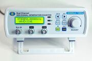
MHINSTEK MHS-5200A startscreen1.jpg | MHINSTEK MHS-5200A startscreen1.jpg|<small>Device, front</small> | ||
MHINSTEK MHS-5200A startscreen2.jpg | MHINSTEK MHS-5200A startscreen2.jpg|<small>Device, front</small> | ||
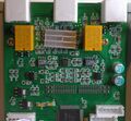
MHINSTEK MHS-5200A base.jpg | MHINSTEK MHS-5200A base.jpg|<small>PCB, top</small> | ||
MHINSTEK MHS-5200A analog.jpg | MHINSTEK MHS-5200A analog.jpg|<small>PCB, analog circuitry</small> | ||
MHINSTEK MHS-5200A back.jpg | MHINSTEK MHS-5200A back.jpg|<small>PCB, bottom</small> | ||
MHINSTEK MHS-5200A CH340.jpg|<small>2015 version PCB, with CH340</small> | |||
</gallery> | </gallery> | ||
== Connection == | == Connection == | ||
The generator has an internal PL2303 USB-to-serial converter. The VID/PID is 067b:2303. Communication parameters | |||
are 57600 bps, 8N1. | The generator has an internal PL2303 USB-to-serial converter. The VID/PID is 067b:2303. Communication parameters are 57600 bps, 8N1. | ||
The earlier 2015 version (firmware 4.22) has CH340 chip for USB-to serial converter, so the VID/PID is 1a86:7523, while rest of the components and functions remain unchanged. | |||
== Protocol == | == Protocol == | ||
| Line 50: | Line 55: | ||
The generator uses a plain text protocol for communication. | The generator uses a plain text protocol for communication. | ||
Each command (''set'' or ''read'') starts with ':' and has to be terminated with a newline, ASCII code 0x0a | Each command (''set'' or ''read'') starts with ':' and has to be terminated with a newline, ASCII code 0x0a (but CRLF, i.e. 0x0d 0x0a, is also accepted). | ||
(but CRLF, i.e. 0x0d 0x0a, is also accepted). | |||
''Set'' commands are acknowledged with an 'ok' response, ''read'' commands echo the request followed by the parameter value. | ''Set'' commands are acknowledged with an 'ok' response, ''read'' commands echo the request followed by the parameter value. | ||
== Resources == | |||
* [http://www.analogzoo.com/2015/08/mhs-5200a-teardown-and-review/ analogzoo.com: MHS-5200A Teardown and Review] | |||
* [http://www.eevblog.com/forum/testgear/mhs-5200a-serial-protocol-reverse-engineered/ eevblog.com: MHS-5200A Serial Protocol Reverse Engineered] | |||
* [https://docs.google.com/document/d/1HbLQ4u87RJkD3Ktyw7k9U7Zh5BPNzbrhMlszNGdXiiY/edit Google docs: MHS5200A Protocol] | |||
Latest revision as of 21:56, 8 February 2021
 | |
| Status | in progress |
|---|---|
| Frequency (user) | 0.01Hz-6MHz/12MHz/20MHz/25Hz |
| Waveforms | sine/square/triangle/sawtooth/arbitrary, TTL rect |
| Amplitude | 20 V (open)/10 V (50 Ohm) (adjustable) |
| Connectivity | USB/serial |
| Website | mhinstek.com |
The MHINSTEK MHS-5200A (-06M/12M/20M/25M) is a dual-channel, standalone function generator. It can be controlled with the push-buttons and the rotary encoder on the front panel, or via a USB interface.
Amplitude and offset voltage can be controlled programmatically.
Device also supports different measurements via 'Ext. In' or 'TTL' channels. It can measure: frequency, counter, pulse width, period and duty cycle.
Hardware (Q3 2016 model)
- FPGA: Lattice MACH XO2 1200HC TQFP-100
- Clock: unknown
- STM8S005K6 8-bit MCU with 32 Kbytes Flash, 16 MHz CPU, integrated 128 byte EEPROM STM8S005K6 product page
- Output stage:
- R2R-ladder 12bit DAC
- Signal/DC-offset sum: AD8017 Op-Amp
- Variable gain amplifier: AD603A
- Power amplifier: AD812A
- Output switch relais: 0db/-20db/off
- 24LC512 I²C EEPROM, 512Kb (64K x 8) for arbitrary waveform data
- 74AHC14D hex inverting schmitt trigger
According to the specs, the hardware should run at 200MS/s, but measurement shows it only runs at ~175MS/s.
Photos
Connection
The generator has an internal PL2303 USB-to-serial converter. The VID/PID is 067b:2303. Communication parameters are 57600 bps, 8N1.
The earlier 2015 version (firmware 4.22) has CH340 chip for USB-to serial converter, so the VID/PID is 1a86:7523, while rest of the components and functions remain unchanged.
Protocol
The generator uses a plain text protocol for communication.
Each command (set or read) starts with ':' and has to be terminated with a newline, ASCII code 0x0a (but CRLF, i.e. 0x0d 0x0a, is also accepted).
Set commands are acknowledged with an 'ok' response, read commands echo the request followed by the parameter value.


