Difference between revisions of "SainSmart DDS140"
SamantazFox (talk | contribs) (→Hardware: Add some of the logic analyzer and signal generator components) |
SamantazFox (talk | contribs) (→Hardware: Fix error made in previous change: the two AD devices in SOIC8 are completely different chips) |
||
| Line 26: | Line 26: | ||
* Signal generator: | * Signal generator: | ||
** '''CMOS Single 8-Channel Analog Multiplexer/Demultiplexer''' [https://www.ti.com/product/CD4052B Texas Instruments CD4052B] ([https://www.ti.com/lit/ds/symlink/cd4052b.pdf datasheet]) | ** '''CMOS Single 8-Channel Analog Multiplexer/Demultiplexer''' [https://www.ti.com/product/CD4052B Texas Instruments CD4052B] ([https://www.ti.com/lit/ds/symlink/cd4052b.pdf datasheet]) | ||
** | ** '''90 MHz Variable Gain Amplifier''' [https://www.analog.com/en/products/ad603.html Analog Devices AD603AR] ([https://www.analog.com/media/en/technical-documentation/data-sheets/AD603.pdf datasheet]) | ||
** '''Dual Operational Amplifier''' [https://www.analog.com/en/products/ad826.html Analag Devices AD826] ([https://www.analog.com/media/en/technical-documentation/data-sheets/AD826.pdf datasheet]) | |||
== Photos - Oscillocope (main unit) == | == Photos - Oscillocope (main unit) == | ||
Latest revision as of 20:46, 26 September 2020

The SainSmart DDS140 is a USB-based, 2-channel oscilloscope with an analog bandwidth of 40MS/s and 200MS/s sampling rate.
Optionally, it also supports usage as signal generator or logic analyzer.
See SainSmart DDS140/Info for more details (such as lsusb -v output) about the device.
Hardware
- Main unit:
- USB: Cypress CY7C68013A-100AXC (FX2LP) (datasheet)
- 64-kbyte I²C EEPROM: Microchip 24LC64I (datasheet)
- Dual 8bit, 100MSPS ADC: MXTronix MXT2088 (datasheet)
- 5x CMOS differential 4-channel analog mux/demux with logic-level conversion: Texas Instruments CD4052BM (datasheet)
- CPLD: Altera MAX II EPM240T100CN (datasheet)
- 64K x 16 CMOS anyc SRAM (8ns): ISSI IS61LV6416-8TI (datasheet)
- Dual voltage comparator: TI LM393 (datasheet)
- 1A low-dropout voltage regulator (3.3V): Advanced Monolithic Systems AMS1117-3.3 (datasheet)
- Crystal: 24MHz (for Cypres FX2)
- Crystal: 80MHz (for Altera MAX II)
- Logic analyzer:
- Octal translating transceiver NXP (Nexperia) LVC4245A (datasheet)
- Signal generator:
- CMOS Single 8-Channel Analog Multiplexer/Demultiplexer Texas Instruments CD4052B (datasheet)
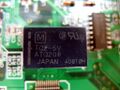
- 90 MHz Variable Gain Amplifier Analog Devices AD603AR (datasheet)
- Dual Operational Amplifier Analag Devices AD826 (datasheet)
Photos - Oscillocope (main unit)
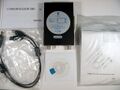
Package contents

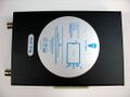
Sticker
Device, top
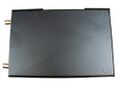
Device, bottom
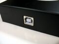
USB
Connectors
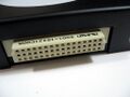
2nd connector
PCB, top
PCB, bottom
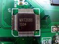
MXT2088
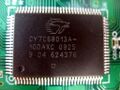
Cypress FX2
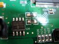
Microchip 24LC64I
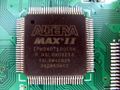
Altera MAXII EPM240T100CN
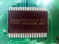
ISSI IS61LV6416-8TI
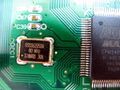
80MHz crystal
AMS1117-3.3
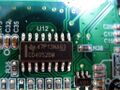
TI CD4502BM
LM393
?
?


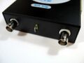
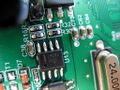
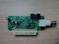
Photos - Signal generator extension

Device, top
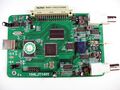
PCB, top
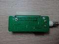
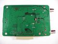
PCB, bottom
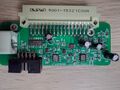
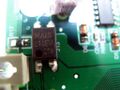
PCB, top (closer view)


.jpg)
Photos - Logic analyzer extension

Device, top
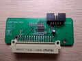
PCB, top
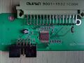
PCB, top (closer view)


.jpg)
Protocol
The protocol used by this device is not based on anything else. It seems to be based on a raw data exchange using a WinUSB pipe.
Sending commands
The DDS140 uses a simple set of command codes (uint8_t, from 0 to 255) that may take arguments.
The host software uses an helper DLL to send theses commands to the device. In this DLL, two functions act as a wrapper around WinUsb_ControlTransfer():
- USBCtrlTransSimple() is used for simple commands, that does not take arguments
- USBCtrlTrans() is used for more complex commands, i.e that takes arguments
It has to be noted that both functions can return data.
The list of currently reversed command codes is available here:
- https://gitlab.com/SamantazFox/dds140-reverse-engineering/-/blob/master/program/Commands_summary.rst (main)
- https://github.com/SamantazFox/dds140-reverse-engineering/blob/master/program/Commands_summary.rst (mirror)
Getting the data back
the process that gets the data back from the device is not well understood yet. It seems that the helper DLL contains a wrapper function around WinUsb_ReadPipe() (for raw buffer read), plus a lot of pre-processing (via the DataPreDisposal() function) which is directly dependant of the GUI settings (graph zoom and position).
This has yet to be reversed.