Difference between revisions of "PCE PCE-322A"
| (One intermediate revision by the same user not shown) | |||
| Line 165: | Line 165: | ||
| 0x01 | | 0x01 | ||
| 0xd2 | | 0xd2 | ||
| 0x''YY'' 0x''XX''colspan="2" | Used memory blocks | | 0x''YY'' 0x''XX'' colspan="2" | Used memory blocks | ||
| 0x''ZZ'' | | | 0x''ZZ'' | Length of last block | ||
| 0x10 or 0x20 | | 0x10 or 0x20 | ||
|} | |} | ||
| Line 188: | Line 188: | ||
| style="width: 3em; text-align: center;" | 11 | | style="width: 3em; text-align: center;" | 11 | ||
|- | |- | ||
| 0x7f | | colspan="2" | 0x7f 0xf7 or 0xff 0xff | ||
| 0x01 | | 0x01 | ||
| 0x00 | | 0x00 | ||
| | | Flags | ||
| colspan="6" | Date | | colspan="6" | Date | ||
|} | |} | ||
- Flags: 0x0a for dB(A) or 0x0c for dB(C). | |||
- Date. Byte 6: Year; Byte 7: Month; Byte 8: Day; Byte 9: 2 bits unknown, 6 bits for Hour; Byte 10: Minutes; Byte 11: Seconds. | |||
== Resources == | == Resources == | ||
* [https://www.pce-instruments.com/english/slot/2/download/60903/manual-sound-level-meter-pce-322-a.pdf User Manual] | * [https://www.pce-instruments.com/english/slot/2/download/60903/manual-sound-level-meter-pce-322-a.pdf User Manual] | ||
* [https://www.silabs.com/products/mcu/Pages/USBtoUARTBridgeVCPDrivers.aspx#mac CP210x USB to UART Bridge VCP Driver for Mac] | |||
[[Category:Device]] | [[Category:Device]] | ||
[[Category:Sound level meter]] | [[Category:Sound level meter]] | ||
[[Category:Supported]] | [[Category:Supported]] | ||
Latest revision as of 19:23, 3 December 2016
 | |
| Status | supported |
|---|---|
| Source code | pce-322a |
| Connectivity | USB/serial |
| Frequency range | 31.5Hz - 8kHz |
| Measurement range (A) | 30dB - 130dB |
| Resolution | 0.1dB |
| Accuracy (94dB@1kHz) | 1.4dB |
| Frequency weighting | A, C |
| Time weighting | F, S |
| Standards | IEC 61672-1 Class 2 |
| Website | pce-instruments.com |
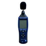
The PCE PCE-322A is an IEC 61672-1 class 2 compliant sound level meter with USB connectivity.
Hardware
TODO
Photos
Protocol
The device communicates at 115200 baud, no parity, 8 data bits, and 1 stop bit (115200/8n1).
Commands
None of the following commands are needed to receive live measurements from the device; see the next section.
The commands are always 2 byte and take no parameters, except for the one requesting memory blocks.
The following commands are supported:
| Command | Description |
|---|---|
| 0xac 0xff | Connect |
| 0xca 0xff | Disconnect |
| 0xaa 0xf1 | Toggle dBA/dBC |
| 0xaa 0xf2 | Toggle Scale (Auto, 30-80, 50-100, 80-130) |
| 0xaa 0xf3 | Toggle Min/Max/Current |
| 0xaa 0xf4 | Toggle Fast/Slow |
| 0xaa 0xf5 | Toggle Hold |
| 0xaa 0xf6 | Toggle Backlight |
| 0xaa 0xf7 | Toggle Time/Date |
| 0xaa 0xf8 | Power Off |
| 0x7e 0x00 ... | Setup Logging (see below) |
| 0xad 0xda | Memory Status |
| 0xd3 0xda 0xXX 0xYY | Transfer YYXX-th block of data (block length: 256) |
| 0xaa 0xc1 | Clear Memory |
Measurements and settings
Current settings and measurements are continually streamed over the serial bus, without any prompting from the PC. Data is encapsulated in packets of 13 bytes. The packets are structured as follows:
| 1 | 2 | 3 | 4 | 5 | 6 | 7 | 8 | 9 | 10 | 11 | 12 | 13 |
| 0x7f | Measurement | Flags/Mode | ? | Date | 0x00 | |||||||
Memory
Setup Request
A recording can be setup remotely (which will start instantly or after pressing a button).
| 1 | 2 | 3 | 4 | 5 | 6 | 7 | 8 | 9 | 10 |
| 0x7e | ? | Interval | Date | Flags | |||||
Status Response
This is the response to the Memory Status (0xad 0xda) command.
| 1 | 2 | 3 | 4 | 5 | 6 | 7 | 8 | 9 |
| 0xd1 | 0x05 | 0x00 | 0x01 | 0xd2 | Used memory blocks | Length of last block | 0x10 or 0x20 | |
Header
Each recording starts with a header:
| 1 | 2 | 3 | 4 | 5 | 6 | 7 | 8 | 9 | 10 | 11 |
| 0x7f 0xf7 or 0xff 0xff | 0x01 | 0x00 | Flags | Date | ||||||
- Flags: 0x0a for dB(A) or 0x0c for dB(C).
- Date. Byte 6: Year; Byte 7: Month; Byte 8: Day; Byte 9: 2 bits unknown, 6 bits for Hour; Byte 10: Minutes; Byte 11: Seconds.
