Difference between revisions of "Hung-Chang DSO-2100"
m (list other scopes with similar names to avoid confusion) |
m (supported now that driver has been merged) |
||
| Line 2: | Line 2: | ||
| image = [[File:HungChang_DSO2100.jpg|180px]] | | image = [[File:HungChang_DSO2100.jpg|180px]] | ||
| name = Hung-Chang DSO-2100 | | name = Hung-Chang DSO-2100 | ||
| status = | | status = supported | ||
| source_code_dir = hung-chang-dso-2100 | | source_code_dir = hung-chang-dso-2100 | ||
| channels = 2 (not simultaneously) | | channels = 2 (not simultaneously) | ||
Revision as of 21:38, 10 September 2015
 | |
| Status | supported |
|---|---|
| Source code | hung-chang-dso-2100 |
| Channels | 2 (not simultaneously) |
| Samplerate | 100MSa/s |
| Analog bandwidth | 30MHz |
| Vertical resolution | 8bits |
| Triggers | edge, composite video |
| Input impedance | 1MΩ‖25pF |
| Memory | 5kpts per channel |
| Display | none |
| Connectivity | parallel port |
| Features | vertical sensitivity: 10mV/div - 5V/div |
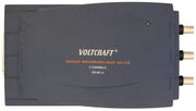
The Hung-Chang DSO-2100 is a 30MHz analog bandwidth 100MS/s parallel port oscilloscope that has been sold under the brand names Protek and Voltcraft. It is not related to the Hantek DSO-2100USB or the Link Instruments DSO-2100 families.
Hardware
- QuickLogic QL2003 pASIC 2 non-volatile FPGA
- Analog Devices ADSP-2105 microcontroller at 12.5MHz
- 2x ISSI IS61C256AH-10J 32kB SRAM
- 2x Harris (Intersil) HI5714/6CB ADC
The hardware does not allow to sample both channels at the same time as the ADCs are always connected to the same signal. There are a lot of design flaws making accurate measurements with this device nearly impossible.
The FPGA handles the low level parallel port protocol so that the microcontroller can interact with the PC using a single byte mailbox in its address space. Samples from SRAM or the ADCs are passed on to the PC by the FPGA without the microcontroller being involved. It also generates the phase shifted sampling clocks from the 50MHz oscillator and increments the SRAM address to take 10240 samples when it detects the correct edge on its trigger input. There is no way to take more samples than that on an event. Most of the 64kB SRAM stays unused.
While the microcontroller is sold as a DSP, its purpose in this device is to handle the state machine that receives the configuration parameters from the PC and to put the FPGA into the requested state. It is also used to copy samples between different regions of the SRAM. Its firmware is ~1000 instructions and can be disassembled using DEADSP. It shows that there are indeed no more commands than those listed on the page linked below.
In 2012 it was still possible to request the schematics from Conrad Electronic as it was sold there with the product number 129208 back in 1999. They will send it on an A3 sheet by snail mail. The schematics are of bad quality with barely readable numbers, missing values, missing or wrong units (i.e. 12KF resistors), and blatant errors (op-amps with positive and negative input connected). It also doesn't tell you that some parts have not been populated. The AX1027 resistor array is (P1) - 70Ω - (P2) - 150Ω - (P3) - 75Ω - (P4) - 45Ω - (P5) - 30Ω - (P6).
Photos
Protocol
See here for more info in the protocol.

