Openbench Logic Sniffer
 | |
| Status | supported |
|---|---|
| Source code | openbench-logic-sniffer |
| Channels | 32 |
| Samplerate | 200MHz |
| Samplerate (state) | ? |
| Triggers | ? |
| Min/max voltage | -0.5 to +7V (buffered), 0-3,3V? (unbuffered) |
| Memory | 24ksamples |
| Compression | RLE (optional) |
| Website | dangerousprototypes.com |
The Openbench Logic Sniffer (OLS) is an FPGA-based logic analyzer, supporting 32 probes for probing up to 100MHz signals and advanced trigger functionality. It is a fully open source device — the circuit design, VHDL code for the FPGA, firmware for the PIC microcontroller and Java-based client software are all freely available. The project is a collaboration between Gadget Factory and Dangerous Prototypes.
The device started life as the Sump Logic Analyzer, which was meant to be run on a Digilent FPGA development board. The Openbench Logic Analyzer unit is a custom-designed board with low cost in mind: it can be bought for $45 from Seeed Studio.
Communication between the board and the PC is done via a USB port connected to a PIC 18F24J50 microcontroller, which presents a standard USB ACM profile. The host handles this as a serial port. The default maximum serial speed of the SUMP Java client is 115200bps, but the USB ACM virtual serial port can be opened at much higher speeds. An overview of the endpoint profile is at Openbench Logic Sniffer/Info.
Full OLS info: dangerousprototypes.com: Open Bench Logic Sniffer
Status:
The sigrok driver does not currently support the "serial" trigger mode. This allows a single trigger to be set (on one or more probes), but with up to 32 stages. The parallel mode is supported, which supports up to 4 distinct trigger stages on any probe.
200MHz demux mode will not work right now, since the driver always expects 32-bit sample values.
Recent hardware (from seeedstudio at least) appears to ship with an FPGA loaded that doesn't support fetching metadata from the device, and causes pulseview to exit with "Caught exception: not applicable" when trying to connect to the device. The source and / or version number of this FPGA core is unknown, if you have purchased a new device and have this problem then you probably want to load the 3.07 demon core to the FPGA using ols-fwloader.
Hardware
- Xilinx Spartan XC3S250E
- Microchip PIC18F24J50-I/30
- Atmel 0952 450B0410 SU or Winbond 25X40 in later versions (see notes below on firmware update tools)
- ON Semiconductor LCX16245
Software tools
- Java logic sniffer client []
- Update packages [1]
- FPGA / PIC firmware updater ols-fwloader - required for later boards with alternative FPGA ROM memory
Photos
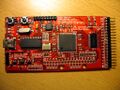
Device, front
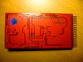
Device, back
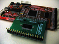
Device with buffer "wing"


Protocol
The communications protocol between the board and the PC is below, taken from the original Sump documentation.
All communication is done using a standard RS232 connection with 8 data bits, 1 stop bit and no parity. The transfer rate is not emulated over USB and can be set to any speed supported by the operating system. Pump-loader, an update utility for the Logic Sniffer ROM chip, uses 921600bps by default. XON/XOFF software flow control is available.
When sending captured data the analyzer will send blocks of four bytes, the first containing the lowest channels. No start or end sequence exists. The host can assume an end of transmission if no data has been received for the duration of one byte.
The protocol used by hardware version 0.5 and older is not covered here. Hardware 0.6 uses protocol version 0, and hardware 0.7 uses protocol version 1. Unless otherwise stated, commands exist in both versions.
The following list provides a short overview of commands understood by the analyzer.
Short Commands
These commands are exactly one byte long.
Reset (0x00)
- Resets the device. Should be sent 5 times when the receiver status is unknown. (It could be waiting for up to four bytes of pending long command data.)
Run (0x01)
- Arms the trigger.
ID (0x02)
- Asks for device identification. The device will respond with four bytes. The first three ("SLA") identify the device. The last one identifies the protocol version which is currently either "0" or "1".
XON (0x11)
- Put transmitter out of pause mode. It will continue to transmit captured data if any is pending. This command is being used for xon/xoff flow control.
XOFF (0x13)
- Put transmitter in pause mode. It will stop transmitting captured data. This command is being used for xon/xoff flow control.
Long Commands
Are five bytes long. The first byte contains the opcode. The bytes are displayed in the order in which they are sent to the serial port starting left. The bits within one byte are displayed most significant first.
Set Trigger Mask (0xc0, 0xc4, 0xc8, 0xcc)
- Defines which trigger values must match. In parallel mode each bit represents one channel, in serial mode each bit represents one of the last 32 samples of the selected channel. The opcodes refer to stage 0-3 in the order given above. (Protocol version 0 only supports stage 0.)

Set Trigger Values (0xc1, 0xc5, 0xc9, 0xcd)
- Defines which values individual bits must have. In parallel mode each bit represents one channel, in serial mode each bit represents one of the last 32 samples of the selected channel. The opcodes refer to stage 0-3 in the order given above. (Protocol version 0 only supports stage 0.)

Set Trigger Configuration (0xc2, 0xc6, 0xca, 0xce)
- Configures the selected trigger stage. The opcodes refer to stage 0-3 in the order given above. The following parameters will be set:
- delay
- If a match occures, the action of the stage is delayed by the given number of samples.
- level
- Trigger level at which the stage becomes active.
- channel
- Channel to be used in serial mode. (0-31 in normal operation; 0-15 when demux flag is set)
- serial
- When set to 1 the stage operates as serial trigger, otherwise it used as parallel trigger.
- start
- When set to 1 a match will start the capturing process. The trigger level will rise on match regardless of this flag. (Command available as of protocol version 1.)
- delay

Set Divider (0x80)
- When x is written, the sampling frequency is set to f = clock / (x + 1).
Set Read & Delay Count (0x81)
- Read Count is the number of samples (divided by four) to read back from memory and sent to the host computer. Delay Count is the number of samples (divided by four) to capture after the trigger fired. A Read Count bigger than the Delay Count means that data from before the trigger match will be read back. This data will only be valid if the device was running long enough before the trigger matched.

Set Flags (0x82)
- Sets the following flags:
- demux
- Enables the demux input module. (Filter must be off.)
- filter
- Enables the filter input module. (Demux must be off.)
- channel groups
- Disable channel group. Disabled groups are excluded from data transmissions. This can be used to speed up transfers. There are four groups, each represented by one bit. Starting with the least significant bit of the channel group field channels are assigned as follows: 0-7, 8-15, 16-23, 24-31.
- external
- Selects the clock to be used for sampling. If set to 0, the internal clock divided by the configured divider is used, and if set to 1, the external clock will be used. Filter and demux are only available with internal clock.
- inverted
- When set to 1, the external clock will be inverted before being used. The inversion causes a delay that may cause problems at very high clock rates. This option only has an effect with external set to 1.
- demux

Known Bugs
RLE mode is currently broken due to samples count being passed in from sigrok is the total samples we will receive, but however the OLS sees this as compressed samples so in turn we can never know how many samples will get send back. Even worse since the buffer is sent backwards you are likely to lose all the data you are trying to trace at the beginning of the session.
Resources
- Open Bench Logic Sniffer (main wiki page)
- Logic Sniffer upgrade procedure