Difference between revisions of "RDing TEMPer"
Jump to navigation
Jump to search
Uwe Hermann (talk | contribs) m |
Uwe Hermann (talk | contribs) m (→Hardware) |
||
| Line 10: | Line 10: | ||
[[File:Rding temper sigrok 2.png|thumb|right|I2C/USB closeup]] | [[File:Rding temper sigrok 2.png|thumb|right|I2C/USB closeup]] | ||
* Main chip: [http://www.dz863.com/datasheet-827607263-TMU3101MS_Usb-Controller/ Tenx TMU3101MS] ([http://www.dz863.com/downloadpdf-cflolocfmpbs-TMU3101MS.pdf datasheet]) | * '''Main chip''': [http://www.dz863.com/datasheet-827607263-TMU3101MS_Usb-Controller/ Tenx TMU3101MS] ([http://www.dz863.com/downloadpdf-cflolocfmpbs-TMU3101MS.pdf datasheet]) | ||
** The markings were removed, but we're relatively sure it's this chip, due to lsusb and pin/feature matching (see below). | ** The markings were removed, but we're relatively sure it's this chip, due to lsusb and pin/feature matching (see below). | ||
* Temperature sensor: [http://www.fairchildsemi.com/pf/FM/FM75.html Fairchild FM75] ([http://www.fairchildsemi.com/ds/FM/FM75.pdf datasheet]), I2C slave address '''0x4f''' | * '''Temperature sensor''': [http://www.fairchildsemi.com/pf/FM/FM75.html Fairchild FM75] ([http://www.fairchildsemi.com/ds/FM/FM75.pdf datasheet]), I2C slave address '''0x4f''' | ||
* I2C EEPROM: Unknown, yet (markings were removed), I2C slave address '''0x50''' | * '''I2C EEPROM''': Unknown, yet (markings were removed), I2C slave address '''0x50''' | ||
* Oscillator: 6MHz | * '''Oscillator''': 6MHz | ||
Main chip pinout: | '''Chip pinouts:''' | ||
<table border="0"> | |||
<tr> | |||
<th>Main chip pinout</th> | |||
<th>I2C EEPROM pinout</th> | |||
</tr> | |||
<tr><td> | |||
{| border="0" cellspacing="0" | |||
|- | |||
| style="width: 10em; font-weight: bold;" align="right" | SCL | |||
| style="width: 2em;" align="right" | 1- | |||
| rowspan="10" valign="top" style="width: 10em; background-color: #333333; color: white;font-weight: bold;" | O | |||
| style="width: 2em;" | -20 | |||
| style="width: 10em; font-weight: bold;" | 3.3V | |||
|- | |||
| style="width: 10em; font-weight: bold;" align="right" | SDA | |||
| style="width: 2em;" align="right" | 2- | |||
| style="width: 2em;" | -19 | |||
| style="width: 10em; font-weight: bold;" | | |||
|- | |||
| style="width: 10em; font-weight: bold;" align="right" | 5V | |||
| style="width: 2em;" align="right" | 3- | |||
| style="width: 2em;" | -18 | |||
| style="width: 10em; font-weight: bold;" | | |||
|- | |||
| style="width: 10em; font-weight: bold;" align="right" | 5V | |||
| style="width: 2em;" align="right" | 4- | |||
| style="width: 2em;" | -17 | |||
| style="width: 10em; font-weight: bold;" | 3.3V | |||
|- | |||
| style="width: 10em; font-weight: bold;" align="right" | 5V | |||
| style="width: 2em;" align="right" | 5- | |||
| style="width: 2em;" | -16 | |||
| style="width: 10em; font-weight: bold;" | 5V | |||
|- | |||
| style="width: 10em; font-weight: bold;" align="right" | 5V | |||
| style="width: 2em;" align="right" | 6- | |||
| style="width: 2em;" | -15 | |||
| style="width: 10em; font-weight: bold;" | LED(5V) | |||
|- | |- | ||
| style="width: 10em; font-weight: bold;" align="right" | GND | |||
| style="width: 2em;" align="right" | 7- | |||
| style="width: 2em;" | -14 | |||
| style="width: 10em; font-weight: bold;" | USB D+ | |||
|- | |- | ||
| | | style="width: 10em; font-weight: bold;" align="right" | 5V | ||
| style="width: 2em;" align="right" | 8- | |||
| style="width: 2em;" | -13 | |||
| style="width: 10em; font-weight: bold;" | USB D- | |||
| 5V | |||
| | |||
| | |||
| | |||
| | |||
| | |||
| | |||
|- | |- | ||
| style="width: 10em; font-weight: bold;" align="right" | 3.3V | |||
| style="width: 2em;" align="right" | 9- | |||
| style="width: 2em;" | -12 | |||
| style="width: 10em; font-weight: bold;" | 5V | |||
|- | |- | ||
| | | style="width: 10em; font-weight: bold;" align="right" | Oscillator | ||
| | | style="width: 2em;" align="right" | 10- | ||
| | | style="width: 2em;" | -11 | ||
| | | style="width: 10em; font-weight: bold;" | Oscillator | ||
| | |||
| | |||
| | |||
|} | |} | ||
</td><td> | |||
{| border="0" | {| border="0" cellspacing="0" | ||
|- | |- | ||
| style="width: 10em; font-weight: bold;" align="right" | GND | |||
| style="width: 2em;" align="right" | 1- | |||
| rowspan="10" valign="top" style="width: 10em; background-color: #333333; color: white;font-weight: bold;" | O | |||
| style="width: 2em;" | -8 | |||
| style="width: 10em; font-weight: bold;" | 3.3V | |||
|- | |- | ||
| GND | | style="width: 10em; font-weight: bold;" align="right" | GND | ||
| GND | | style="width: 2em;" align="right" | 2- | ||
| GND | | style="width: 2em;" | -7 | ||
| | | style="width: 10em; font-weight: bold;" | GND | ||
| | |||
| | |- | ||
| GND | | style="width: 10em; font-weight: bold;" align="right" | GND | ||
| | | style="width: 2em;" align="right" | 3- | ||
| style="width: 2em;" | -6 | |||
| style="width: 10em; font-weight: bold;" | SCL | |||
|- | |||
| style="width: 10em; font-weight: bold;" align="right" | GND | |||
| style="width: 2em;" align="right" | 4- | |||
| style="width: 2em;" | -5 | |||
| style="width: 10em; font-weight: bold;" | SDA | |||
|} | |} | ||
</td></tr></table> | |||
See [http://sigrok.org/gitweb/?p=sigrok-dumps.git;a=tree;f=i2c/rding_temper;hb=HEAD these example sigrok captures] for the I2C, USB, and LED traffic going on while the device is queried from the PC (see also screenshots on the right-hand side). | See [http://sigrok.org/gitweb/?p=sigrok-dumps.git;a=tree;f=i2c/rding_temper;hb=HEAD these example sigrok captures] for the I2C, USB, and LED traffic going on while the device is queried from the PC (see also screenshots on the right-hand side). | ||
Example usage: | '''Example usage:''' | ||
<small> | <small> | ||
Revision as of 23:50, 1 November 2012

The RDing TEMPer is a USB-based temperature logger.
See RDing TEMPer/Info for more details (such as lsusb -vvv output) about the device.
Hardware


- Main chip: Tenx TMU3101MS (datasheet)
- The markings were removed, but we're relatively sure it's this chip, due to lsusb and pin/feature matching (see below).
- Temperature sensor: Fairchild FM75 (datasheet), I2C slave address 0x4f
- I2C EEPROM: Unknown, yet (markings were removed), I2C slave address 0x50
- Oscillator: 6MHz
Chip pinouts:
| Main chip pinout | I2C EEPROM pinout | ||||||||||||||||||||||||||||||||||||||||||||||||||||||||||
|---|---|---|---|---|---|---|---|---|---|---|---|---|---|---|---|---|---|---|---|---|---|---|---|---|---|---|---|---|---|---|---|---|---|---|---|---|---|---|---|---|---|---|---|---|---|---|---|---|---|---|---|---|---|---|---|---|---|---|---|
|
|
See these example sigrok captures for the I2C, USB, and LED traffic going on while the device is queried from the PC (see also screenshots on the right-hand side).
Example usage:
$ sigrok-cli -i rding_temper_i2c_usb_led_sensor_5s.sr -a i2c:sda=0:scl=1
i2c: "START"
i2c: "ADDRESS READ" "0x4f"
i2c: "ACK"
i2c: "DATA READ" "0x1d"
i2c: "ACK"
i2c: "DATA READ" "0x80"
i2c: "ACK"
i2c: "STOP"
$ sigrok-cli -i rding_temper_i2c_usb_led_sensor_5s.sr -a usb:dm=3:dp=4:signalling=low-speed
usb: "SYNC INVALID!" "001001001100100"
usb: "SYNC INVALID!" "000000000000110000000111111100100000000010001"
usb: "SYNC INVALID!" "0000000000011100000011000000000000000000000000000000000000000000000000000000000000000000000000000000000000000000000000111111001000101111"
usb: "SYNC INVALID!" "000000000000001001000010011"
usb: "OUT DEV 47 EP 0" "00000001100001111111010000001001"
usb: "DATA1 00 00 00 00 00 00 00 00 " "000000011101001000000000000000000000000000000000000000000000000000000000000000001111110100101111"
usb: "SYNC INVALID!" "00000000101001011"
usb: "OUT DEV 47 EP 0" "00000001100001111111010000001001"
usb: "DATA0 00 00 00 00 00 00 00 00 " "000000011100001100000000000000000000000000000000000000000000000000000000000000001111110100101111"
usb: "SYNC INVALID!" "00000000101001011"
usb: "IN DEV 47 EP 0" "00000001100101101111010000001001"
usb: "DATA1 " "00000001110100100000000000000000"
usb: "ACK " "0000000101001011"
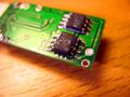
Photos
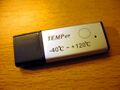
Device, front
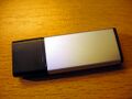
Device, back
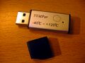
Device, USB
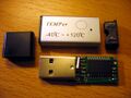
Device, opened
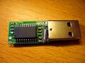
PCB, front
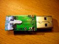
PCB, back
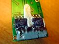
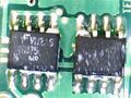
Sensor, EEPROM
Random pads on the side
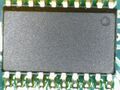
Main chip, microscope
Sensor, microscope


Protocol
HID-based.
Resources
- Relavak Labs: TEMPer Temperature Sensor Linux Driver (libusb software)
- LinuxJournal: Hack and / - Temper Temper (article about Device::USB::PCSensor::HidTEMPer perl module)
- Polarnight blog: TEMPer USB Temperature Sensor – Inside! (a teardown of an older TEMPer version)
- bil: Software to support the TEMPer USB thermistor (blog post)
- Jonathan Gazeley: Nagios plugin for TEMPer USB thermometer (also: TEMPer2.c, code for the USB-to-serial version)
- Tollef Fog Heen's blog: Kernel patches and the TEMPer USB thermometer (also: TEMPer.c)
- No Feature Left behind: Taking advantage of your TEMPer 1.0 USB device (C#, .NET)
- Device::USB::PCSensor::HidTEMPer (Perl)
- Eclectic Security: Dirt cheap USB Temperature Sensor with python SMS alerting system (also: Pytemp2sms)
- CircuitDB: Cheap temperature logging
- RJL: Using Cacti to measure temperatures
- SourceForge: UTAC (C#, .NET)
- Github: TEMPered, temperhum, HID-TEMPerHUM, rbtemper, TEMPer1X, temper1, temper, temper, temper-hum-hid