Difference between revisions of "RockyLogic Ant8"
Jump to navigation
Jump to search
Uwe Hermann (talk | contribs) (Device info.) |
Uwe Hermann (talk | contribs) m |
||
| (14 intermediate revisions by 3 users not shown) | |||
| Line 1: | Line 1: | ||
{{Infobox logic analyzer | |||
| image = [[File:Rockylogic_ant8.png|180px]] | |||
| name = RockyLogic Ant8 | |||
| status = planned | |||
| source_code_dir = | |||
| channels = 8 | |||
| samplerate = 500MHz | |||
| samplerate_state = ? | |||
| triggers = ? | |||
| voltages = ? | |||
| memory = ? | |||
| compression = ? | |||
| website = [http://www.rockylogic.com/products/ant8.html rockylogic.com] | |||
}} | |||
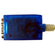
The [http://www.rockylogic.com/products/ant8.html RockyLogic Ant8] is a USB-based, 8-channel logic analyzer with up to 500MHz sampling rate. | |||
== | See [[RockyLogic_Ant8/Info]] for more details (such as '''lsusb -v''' output) about the device. | ||
== Hardware == | |||
* Xilinx Spartan-II XC2S30 VQ100AMS0341 (FPGA; 13,824 total distributed RAM bits, 24K total block RAM) | * Xilinx Spartan-II XC2S30 VQ100AMS0341 (FPGA; 13,824 total distributed RAM bits, 24K total block RAM) | ||
| Line 14: | Line 29: | ||
* 20MHz crystal (for the FPGA) | * 20MHz crystal (for the FPGA) | ||
== | == Photos == | ||
<gallery> | |||
File:Rockylogic ant8 device.jpg|<small>RockyLogic Ant8</small> | |||
File:Rockylogic ant8 device with probes.jpg|<small>Device with probes</small> | |||
File:Rockylogic ant8 pcb front.jpg|<small>PCB, front</small> | |||
File:Rockylogic ant8 pcb back.jpg|<small>PCB, back</small> | |||
File:Rockylogic ant8 ftdi ft245bm.jpg|<small>FTDI FT245BM</small> | |||
File:Rockylogic ant8 atmel 93c66 eeprom.jpg|<small>Atmel 93C66 EEPROM</small> | |||
File:Rockylogic ant8 xilinx spartan xc2s30 fpga.jpg|<small>Xilinx XC2S30</small> | |||
File:Rockylogic ant8 xilinx xc9572xl cpld.jpg|<small>Xilinx XC9572XL</small> | |||
File:Rockylogic ant8 idt ics501m.jpg|<small>IDT ICS501M</small> | |||
File:Rockylogic ant8 national lp2989 im2 5.jpg|<small>National LP2989</small> | |||
File:Rockylogic ant8 on hc00a pgzi.jpg|<small>ON HC00A</small> | |||
</gallery> | |||
See also [https://secure.flickr.com/photos/uwehermann/sets/72157628456436719/ this flickr set] for more PCB photos of the device. | |||
== Protocol == | |||
See [[RockyLogic Ant18e#Protocol|the Ant18e wiki page]] for a description of the Ant8/Ant16/Ant18e protocol. | |||
== DIY Ant8 probe cable == | |||
The Ant8 cable shipped with the device doesn't have the best quality probes/hooks, but you can easily make your own cable where you can attach the better-quality E-Z Hooks. | |||
'''Requirements:''' | |||
* 10-pin colored ribbon cable, such as [http://www.reichelt.de/Flachbandkabel/AWG-28-10F-3M/index.html?;ACTION=3;LA=2;ARTICLE=47668;GROUPID=3328;artnr=AWG+28-10F+3M this one]. | |||
** The colors match the one shipped with the Ant8 (white, gray, purple, blue, green, yellow, orange, red, brown) if you remove the 10th (black) lead. The brown lead is GND. | |||
* A "SUB-D" connector where you can attach the ribbon cable, such as [http://www.reichelt.de/SUB-D-Flachbandverbinder/D-SUB-BU-09FB/index.html?;ACTION=3;LA=2;ARTICLE=6951;GROUPID=3204;artnr=D-SUB+BU+09FB this one]. | |||
* 5 female-female jumper wires, such as [http://www.komputer.de/zen/index.php?main_page=product_info&cPath=31&products_id=77 these ones], which we'll cut into two halves to get 10 female connectors (only 9 needed). | |||
* 9 short pieces of heat-shrink tubing. | |||
* 9 E-Z Hook grippers/hooks to attach to the cable. | |||
'''Photos:''' | |||
<gallery> | |||
File:Diy rockylogic ant8 cable connector.jpg|<small>Sub-D connector</small> | |||
File:Diy rockylogic ant8 cable ribbon cable.jpg|<small>Ribbon cable (black lead removed)</small> | |||
File:Diy rockylogic ant8 cable cable connected.jpg|<small>Connected cable</small> | |||
File:Diy rockylogic ant8 cable jumper wires.jpg|<small>Jumper wires</small> | |||
File:Diy rockylogic ant8 cable jumper wires cut.jpg|<small>Cut jumper wires</small> | |||
File:Diy rockylogic ant8 cable heat shrink tubing.jpg|<small>Heat-shrink tubing</small> | |||
File:Diy rockylogic ant8 cable prepare heatshrink tubing.jpg|<small>Prepared heat-shrink tubing</small> | |||
File:Diy rockylogic ant8 cable solder jumper wires.jpg|<small>Soldered jumper-wires</small> | |||
File:Diy rockylogic ant8 cable heated up.jpg|<small>Heated up</small> | |||
File:Diy rockylogic ant8 cable finished with ezhooks.jpg|<small>Finished cable with E-Z Hooks</small> | |||
</gallery> | |||
See also [https://secure.flickr.com/photos/uwehermann/sets/72157628685898881/ this flickr set] for more photos. | |||
== Resources == | |||
TODO. | |||
[[Category:Device]] | |||
[[Category:Logic analyzer]] | |||
[[Category:Planned]] | |||
Latest revision as of 14:47, 19 September 2014
 | |
| Status | planned |
|---|---|
| Channels | 8 |
| Samplerate | 500MHz |
| Samplerate (state) | ? |
| Triggers | ? |
| Min/max voltage | ? |
| Memory | ? |
| Compression | ? |
| Website | rockylogic.com |
The RockyLogic Ant8 is a USB-based, 8-channel logic analyzer with up to 500MHz sampling rate.
See RockyLogic_Ant8/Info for more details (such as lsusb -v output) about the device.
Hardware
- Xilinx Spartan-II XC2S30 VQ100AMS0341 (FPGA; 13,824 total distributed RAM bits, 24K total block RAM)
- Xilinx XC9572XL VQ44BMN0345 10C (CPLD; 10ns pin-to-pin logic delays)
- FTDI FT245BM (USB FIFO device)
- IDT ICS501M (clock multiplier)
- Atmel AT93C66 (4kB, three-wire serial EEPROM)
- ON Semiconductor (On) HC00A PGZI (quad 2-input NAND gate)
- National/TI LP2989 (marking: 33AB 2989 IM-2.5) (micropower/low-noise, 500mA ultra low-dropout regulator)
- 20MHz crystal (for the FPGA)
Photos
See also this flickr set for more PCB photos of the device.
Protocol
See the Ant18e wiki page for a description of the Ant8/Ant16/Ant18e protocol.
DIY Ant8 probe cable
The Ant8 cable shipped with the device doesn't have the best quality probes/hooks, but you can easily make your own cable where you can attach the better-quality E-Z Hooks.
Requirements:
- 10-pin colored ribbon cable, such as this one.
- The colors match the one shipped with the Ant8 (white, gray, purple, blue, green, yellow, orange, red, brown) if you remove the 10th (black) lead. The brown lead is GND.
- A "SUB-D" connector where you can attach the ribbon cable, such as this one.
- 5 female-female jumper wires, such as these ones, which we'll cut into two halves to get 10 female connectors (only 9 needed).
- 9 short pieces of heat-shrink tubing.
- 9 E-Z Hook grippers/hooks to attach to the cable.
Photos:
See also this flickr set for more photos.
Resources
TODO.


