UNI-T UT612
 | |
| Status | in progress |
|---|---|
| Source code | serial-lcr |
| Counts | 20000 |
| IEC 61010-1 | — |
| Connectivity | USB (HID) |
| Measurements | resistance, capacitance, inductance, equivalents |
| Features | autorange, rel, data-hold, auto-poweroff, self-calibration |
| Website | uni-trend.com |
The UNI-T UT612 is a 20000 counts, dual-display, LCR meter with USB/HID connectivity.
See UNI-T UT612/Info for more details (such as lsusb -v output) about the device.
Status: The serial-lcr driver successfully communicates with the UNI-T UT612 when a CDC adapter is connected to the ES51919 chip's UART signals. Transparent communication with the CP2110 serial-over-HID chip is not yet available but is being worked on.
Hardware
- LCR meter chipset: Cyrustek ES51919 (datasheet)
- HID USB to UART bridge: Silicon Labs CP2110 (datasheet)
The ES51919/51920 chipset is found in other LCR meters, too. The chipset communicates via UART (TX only).
The CP2110 USB serial-over-HID chip resides on a separate breakout board, and is connected to the LCR "mainboard" via a three wire flying cable. Red(!) is GND, green is the meter's TX signal, RX is not connected, yellow is Vcc from USB.
Photos
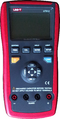
front
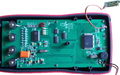
PCB, bird's view
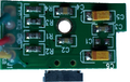
USB breakout, bottom
USB breakout, socket
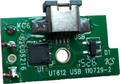
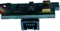
USB breakout, top
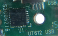
USB breakout, chip


Protocol
The protocol for the ES51919 was reverse engineered as part of the DER-EE 5000 driver that uses the same chipset. Below is the excerpt from the source code.
Public official documentation does not contain the protocol description, so this is all based on reverse engineering.

Packet structure (17 bytes):

0x00: header1 ?? (0x00)

0x01: header2 ?? (0x0d)

0x02: flags
        bit 0 = hold enabled
        bit 1 = reference shown (in delta mode)
        bit 2 = delta mode
        bit 3 = calibration mode
        bit 4 = sorting mode
        bit 5 = LCR mode
        bit 6 = auto mode
        bit 7 = parallel measurement (vs. serial)

0x03: config
        bit 0-4 = ??? (0x10)
        bit 5-7 = test frequency
                    0 = 100 Hz
                    1 = 120 Hz
                    2 = 1 kHz
                    3 = 10 kHz
                    4 = 100 kHz
                    5 = 0 Hz (DC)

0x04: tolerance (sorting mode)
        0 = not set
        3 = +-0.25%
        4 = +-0.5%
        5 = +-1%
        6 = +-2%
        7 = +-5%
        8 = +-10%
        9 = +-20%
       10 = -20+80%

0x05-0x09: primary measurement
  0x05: measured quantity
          1 = inductance
          2 = capacitance
          3 = resistance
          4 = DC resistance
  0x06: measurement MSB  (0x4e20 = 20000 = outside limits)
  0x07: measurement LSB
  0x08: measurement info
          bit 0-2 = decimal point multiplier (10^-val)
          bit 3-7 = unit
                      0 = no unit
                      1 = Ohm
                      2 = kOhm
                      3 = MOhm
                      5 = uH
                      6 = mH
                      7 = H
                      8 = kH
                      9 = pF
                      10 = nF
                      11 = uF
                      12 = mF
                      13 = %
                      14 = degree

0x09: measurement status
          bit 0-3 = status
                      0 = normal (measurement shown)
                      1 = blank (nothing shown)
                      2 = lines ("----")
                      3 = outside limits ("OL")
                      7 = pass ("PASS")
                      8 = fail ("FAIL")
                      9 = open ("OPEn")
                     10 = shorted ("Srt")
          bit 4-6 = ??? (maybe part of same field with 0-3)
          bit 7   = ??? (some independent flag)

0x0a-0x0e: secondary measurement
  0x0a: measured quantity
          0 = none
          1 = dissipation factor
          2 = quality factor
          3 = parallel AC resistance / ESR
          4 = phase angle
  0x0b-0x0e: like primary measurement

0x0f: footer1 (0x0d)

0x10: footer2 (0x0a)
Resources
- Official UNI-T UT612 related documents (manual, software, ...)
- eevblog.com: Review and tear-down of UNI-T UT612 LCR meter