Difference between revisions of "UNI-T UT372"
(→Protocol: Extra time digit) |
m (Fixed UT-372 URL) |
||
| (4 intermediate revisions by 2 users not shown) | |||
| Line 1: | Line 1: | ||
{{Infobox multimeter | {{Infobox multimeter | ||
| image = [[File: | | image = [[File:Uni-t ut372 mugshot.png|180px]] | ||
| name = UNI-T UT372 | | name = UNI-T UT372 | ||
| status = | | status = supported | ||
| source_code_dir = | | source_code_dir = uni-t-dmm | ||
| counts = 99999 | |||
| categories = | |||
| connectivity = USB | | connectivity = USB | ||
| website = [http:// | | measurements = rpm, counts | ||
| features = | |||
| website = [http://uni-trend.com/productsdetail.aspx?ProductsID=789&ProductsCateId=804&CateId=804 uni-trend.com] | |||
}} | }} | ||
| Line 14: | Line 18: | ||
* [http://www.silabs.com/Support%20Documents/TechnicalDocs/C8051F313-short.pdf Silicon Labs C8051F313] MCU | * [http://www.silabs.com/Support%20Documents/TechnicalDocs/C8051F313-short.pdf Silicon Labs C8051F313] MCU | ||
* [http://www.goldenviewdisplay.com/pdf/LCD_controllers/ht1621.pdf Holtek HT1621B] LCD controller | * [http://www.goldenviewdisplay.com/pdf/LCD_controllers/ht1621.pdf Holtek HT1621B] LCD controller | ||
* [[ | * [[WCH CH9325]] USB UART interface | ||
The unit includes a built in laser pointer for aiming at a reflective target, and a tripod fitting to allow stable mounting. | The unit includes a built in laser pointer for aiming at a reflective target, and a tripod fitting to allow stable mounting. | ||
| Line 21: | Line 25: | ||
<gallery> | <gallery> | ||
File:UT372_front.jpg | File:UT372_front.jpg|<small>Device, front</small> | ||
File:UT372_back.jpg | File:UT372_back.jpg|<small>Device, back</small> | ||
File:UT372_pcb.jpg | File:UT372_pcb.jpg|<small>PCB, top</small> | ||
</gallery> | </gallery> | ||
| Line 32: | Line 36: | ||
The packet is processed to turn it into a valid hex string - any character with an ASCII value above 0x39 is shifted up by 7 characters, putting it into the range 'A' to 'F'. | The packet is processed to turn it into a valid hex string - any character with an ASCII value above 0x39 is shifted up by 7 characters, putting it into the range 'A' to 'F'. | ||
The first character seems to be ignored. The next 5 pairs of characters represent the RPM (least significant digit first). The next 5 pairs of characters represent the time (least significant digit first). The remaining | The first character seems to be ignored. The next 5 pairs of characters represent the RPM (least significant digit first). The next 5 pairs of characters represent the time (least significant digit first). The final 2 pairs of characters represent the remaining segments of the display. | ||
Each pair of characters, when interpreted as a single hex byte, is a bitfield representing the on/off state of segments on the display. A look-up table is provided below. Setting the most significant bit indicates that a decimal point is placed after that digit. | Each pair of characters, when interpreted as a single hex byte, is a bitfield representing the on/off state of segments on the display. A look-up table is provided below. Setting the most significant bit indicates that a decimal point is placed after that digit. | ||
{| border="0" class="alternategrey sigroktable sortable" | === LCD character lookup === | ||
{| border="0" style="font-size: smaller" class="alternategrey sigroktable sortable" | |||
|- | |- | ||
! style="width: 5em; text-align: left;" | String | ! style="width:5em; text-align: left;" | String | ||
! style="text-align: left;" | Hex | ! style="text-align: left;" | Hex byte | ||
! style="text-align: left;" | Character | ! style="text-align: left;" | Character | ||
|- | |- | ||
| Line 85: | Line 91: | ||
| 0x0B | | 0x0B | ||
| L | | L | ||
|- | |||
|} | |||
=== Other display segments === | |||
{| border="0" style="font-size: smaller" class="alternategrey sigroktable sortable" | |||
|- | |||
! style="width:5em; text-align: left;" | Bit (LSB #0) | |||
! style="text-align: left;" | First byte | |||
! style="text-align: left;" | Second byte | |||
|- | |||
| 0 | |||
| - | |||
| RPM | |||
|- | |||
| 1 | |||
| BATT | |||
| COUNT | |||
|- | |||
| 2 | |||
| HOLD | |||
| - | |||
|- | |||
| 3 | |||
| - | |||
| - | |||
|- | |||
| 4 | |||
| LED | |||
| MAX | |||
|- | |||
| 5 | |||
| - | |||
| MIN | |||
|- | |||
| 6 | |||
| - | |||
| AVE | |||
|- | |||
| 7 | |||
| - | |||
| - | |||
|- | |- | ||
|} | |} | ||
| Line 95: | Line 143: | ||
[[Category:Device]] | [[Category:Device]] | ||
[[Category:Tachometer]] | [[Category:Tachometer]] | ||
[[Category: | [[Category:Supported]] | ||
Latest revision as of 20:59, 20 April 2017
 | |
| Status | supported |
|---|---|
| Source code | uni-t-dmm |
| Counts | 99999 |
| Connectivity | USB |
| Measurements | rpm, counts |
| Website | uni-trend.com |
The UNI-T UT372 is a digital tachometer with USB connectivity.
Hardware
- Silicon Labs C8051F313 MCU
- Holtek HT1621B LCD controller
- WCH CH9325 USB UART interface
The unit includes a built in laser pointer for aiming at a reflective target, and a tripod fitting to allow stable mounting.
Photos
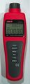
Device, front
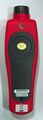
Device, back
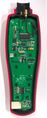
PCB, top
Protocol
The MCU transmits serial data to the CH9325 at 2400 baud. A packet is 27 bytes of ASCII data ending in CR, LF.
The packet is processed to turn it into a valid hex string - any character with an ASCII value above 0x39 is shifted up by 7 characters, putting it into the range 'A' to 'F'.
The first character seems to be ignored. The next 5 pairs of characters represent the RPM (least significant digit first). The next 5 pairs of characters represent the time (least significant digit first). The final 2 pairs of characters represent the remaining segments of the display.
Each pair of characters, when interpreted as a single hex byte, is a bitfield representing the on/off state of segments on the display. A look-up table is provided below. Setting the most significant bit indicates that a decimal point is placed after that digit.
LCD character lookup
| String | Hex byte | Character |
|---|---|---|
| "7;" | 0x7B | 0 |
| "60" | 0x60 | 1 |
| "5>" | 0x5E | 2 |
| "7<" | 0x7C | 3 |
| "65" | 0x65 | 4 |
| "3=" | 0x3D | 5 |
| "3?" | 0x3F | 6 |
| "70" | 0x70 | 7 |
| "7?" | 0x7F | 8 |
| "7=" | 0x7D | 9 |
| "0;" | 0x0B | L |
Other display segments
| Bit (LSB #0) | First byte | Second byte |
|---|---|---|
| 0 | - | RPM |
| 1 | BATT | COUNT |
| 2 | HOLD | - |
| 3 | - | - |
| 4 | LED | MAX |
| 5 | - | MIN |
| 6 | - | AVE |
| 7 | - | - |