Difference between revisions of "UNI-T UT325"
(dual display meter but only one value in the serial packet) |
Uwe Hermann (talk | contribs) (Linkfix, infobox, image captions.) |
||
| Line 1: | Line 1: | ||
[[File:Uni-t ut325 front.jpg| | {{Infobox multimeter | ||
| image = [[File:Uni-t ut325 front.jpg|180px]] | |||
| name = UNI-T UT325 | |||
| status = supported | |||
| source_code_dir = uni-t-ut32x | |||
| counts = | |||
| categories = | |||
| connectivity = | |||
| measurements = temperature | |||
| features = data hold, min/max, backlight | |||
| website = [http://www.uni-trend.com/html/product/Environmental/Environmental_Tester/UT320_Contact_Type/UT325.html uni-trend.com] | |||
}} | |||
The | The '''UNI-T UT325''' is a logging thermometer with two thermocouple inputs and USB connectivity. It supports K,J,T,E,R,S,N thermocouple types. | ||
See [[UNI-T UT325/Info]] for more details about the device. | See [[UNI-T UT325/Info]] for more details (such as '''lsusb -v''' output) about the device. | ||
The device sends temperature measurements at 6Hz to the host. | The device sends temperature measurements at 6Hz to the host. | ||
| Line 9: | Line 20: | ||
== Hardware == | == Hardware == | ||
* [http://www.msp430.net/msp430fe427.pdf Texas Instruments | * [http://www.msp430.net/msp430fe427.pdf Texas Instruments MSP430FE427] (MSP430) microcontroller with 32KiB flash. | ||
* ATMEL 16KiB EEPROM, various models. | * ATMEL 16KiB EEPROM, various models. | ||
* [[WCH CH9325]] USB interface chip. | * [[WCH CH9325]] USB interface chip. | ||
| Line 17: | Line 28: | ||
<gallery> | <gallery> | ||
File:Uni-t ut325 packaging.jpg | File:Uni-t ut325 packaging.jpg|<small>Packaging</small> | ||
File:Uni-t ut325 perspective.jpg | File:Uni-t ut325 perspective.jpg|<small>Device, side</small> | ||
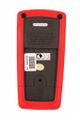
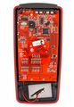
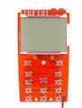
File:Uni-t ut325 front.jpg | File:Uni-t ut325 front.jpg|<small>Device, front</small> | ||
File:Uni-t ut325 top.jpg | File:Uni-t ut325 top.jpg|<small>Device, top</small> | ||
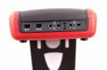
File:Uni-t ut325 back wo bail.jpg | File:Uni-t ut325 back wo bail.jpg|<small>Device, back</small> | ||
File:Uni-t ut325 back battery.jpg | File:Uni-t ut325 back battery.jpg|<small>Device, battery</small> | ||
File:Uni-t ut325 case open.jpg | File:Uni-t ut325 case open.jpg|<small>Device, open</small> | ||
File:Uni-t ut325 fpanel back.jpg | File:Uni-t ut325 fpanel back.jpg|<small>Front panel, back</small> | ||
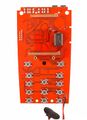
File:Uni-t ut325 pcb bottom.jpg | File:Uni-t ut325 pcb bottom.jpg|<small>PCB, bottom</small> | ||
File:Uni-t ut325 pcb front w display.jpg | File:Uni-t ut325 pcb front w display.jpg|<small>PCB, top, display</small> | ||
File:Uni-t ut325 pcb front.jpg | File:Uni-t ut325 pcb front.jpg|<small>PCB, top</small> | ||
File:UNI-T UT325 LCD.png | File:UNI-T UT325 LCD.png|<small>LCD</small> | ||
File:UNI-T UT325 USB cable connector.png | File:UNI-T UT325 USB cable connector.png|<small>USB connector</small> | ||
</gallery> | </gallery> | ||
Revision as of 20:16, 15 June 2019
 | |
| Status | supported |
|---|---|
| Source code | uni-t-ut32x |
| Measurements | temperature |
| Features | data hold, min/max, backlight |
| Website | uni-trend.com |
The UNI-T UT325 is a logging thermometer with two thermocouple inputs and USB connectivity. It supports K,J,T,E,R,S,N thermocouple types.
See UNI-T UT325/Info for more details (such as lsusb -v output) about the device.
The device sends temperature measurements at 6Hz to the host.
Hardware
- Texas Instruments MSP430FE427 (MSP430) microcontroller with 32KiB flash.
- ATMEL 16KiB EEPROM, various models.
- WCH CH9325 USB interface chip.
- Holtek HT1621B LCD driver.
Photos
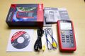
Packaging
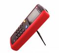
Device, side
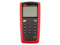
Device, front
Device, top
Device, back
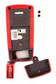
Device, battery
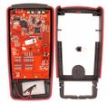
Device, open
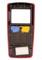
Front panel, back
PCB, bottom
PCB, top, display
PCB, top
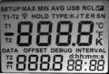
LCD
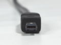
USB connector


Protocol
The device communicates with the host via a WCH CH9325 USB interface chip. See the protocol section of that page to extract the protocol as described here.
Commands
| Byte | Description |
|---|---|
| 0x01 | Start sending realtime data |
| 0x02 | Stop sending data |
| 0x03 | Set device to "debug" mode (calibration mode) |
| 0x04 | When sent twice in succession, clears all stored memory |
| 0x07 | Start sending stored data |
Received data
Temperature is encoded as ASCII digits. The number represents the temperature * 10. A negative sign is represented by 0x3b (ASCII semicolon). Unused digits are represented by 0x3a (ASCII colon), and should be ignored. A completely invalid measurement is represented as four times 0x3b (ASCII semicolon). This happens when no probe is connected.
The data comes out of the USB HID encoding in packets of 19 bytes each:
| Byte | Description |
|---|---|
| 0 | ASCII digit: 0=measurement from memory, 2=realtime measurement, 6=unknown |
| 1-4 | Temperature. |
| 5 | ASCII digit 1-3, representing the measurement unit: Celcius, Fahrenheit or Kelvin respectively, or 0 when unknown (in recall mode; unit is not stored.) |
| 6-7 | Number of stored reading in recall mode, as ASCII digits 00-99. Always 00 in realtime mode. |
| 8 | Unknown, always ASCII digit 0 |
| 9-10 | Hour, as ASCII digits. |
| 11-12 | Minutes, as ASCII digits. |
| 13 | Selected probe, as ASCII digits 0-3: 0=T1, 1=T2, 2=T1-T2 (T1 on main display, 3=T1-T2 (T2 on main display). |
| 14-15 | unknown |
| 16 | Unknown, always ASCII digit 1 |
| 17-18 | Always 0x0d 0x0a (CRLF), denoting end of packet.
|
Driver status
The device does not send the status of the Hold button, or of the Max/Min/Avg setting, thus these are not reported back to a frontend.
Although the meter features dual display, the serial packet only communicates the content of the main display. This display reflects the user's choice (T1, T2, or T1-T2, selected by means of pressing buttons), but the remote (i.e the PC side driver) cannot pick which value to display.