Difference between revisions of "SainSmart DDS120"
Uwe Hermann (talk | contribs) |
|||
| (13 intermediate revisions by 2 users not shown) | |||
| Line 1: | Line 1: | ||
[[File:Dds120 mugshot.png| | {{Infobox oscilloscope | ||
| image = [[File:Dds120 mugshot.png|180px]] | |||
| name = SainSmart DDS120 | |||
| status = supported | |||
| source_code_dir = hantek-6xxx | |||
| channels = 2 | |||
| samplerate = 50MHz | |||
| samplerate_equiv = | |||
| bandwidth = 20MHz | |||
| vertical_resolution = 8bit | |||
| triggers = none (SW-only) | |||
| input_impedance = 1MΩ‖25pF | |||
| memory = none | |||
| display = none | |||
| connectivity = USB | |||
| features = | |||
| website = [http://www.sainsmart.com/sainsmart-dds-120-20m-50m-s-virtual-oscilloscope-silver.html sainsmart.com] | |||
}} | |||
The | The '''SainSmart DDS120''' is a USB-based, 2-channel oscilloscope with an analog bandwidth of 20MS/s and 50MS/s sampling rate. | ||
This device appears to be a rebadge of the [[Rocktech BM102]] (or vice versa). The [[SainSmart DDS120/Info|lsusb]] is exactly the same, the PCB is exactly the same (both have a "656517" and "102LJT1402" silkscreen), and the components used appear to be the same as well. | |||
The device was apparently [https://translate.google.de/translate?sl=auto&tl=en&js=y&prev=_t&hl=en&ie=UTF-8&u=https%3A%2F%2Fweb.archive.org%2Fweb%2F20140520231246%2Fhttp%3A%2F%2Fbbs.21ic.com%2Ficview-350047-1-1.html&edit-text=&act=url created by someone named "buudai"] in 2012 (also reflected in the [[SainSmart DDS120/Info|lsusb]] and in the former [https://web.archive.org/web/20130403082149/http://www.buudai.com/ buudai.com] website). | |||
See [[SainSmart DDS120/Info]] for more details (such as '''lsusb -v''' output) about the device. | See [[SainSmart DDS120/Info]] for more details (such as '''lsusb -v''' output) about the device. | ||
== Hardware == | |||
* '''USB''': [http://www.cypress.com/documentation/datasheets/cy7c68013a-cy7c68014a-cy7c68015a-cy7c68016a-ez-usb-fx2lp-usb Cypress CY7C68013A-100AXC] (FX2LP) ([http://www.cypress.com/file/138911/download datasheet]) | * '''USB''': [http://www.cypress.com/documentation/datasheets/cy7c68013a-cy7c68014a-cy7c68015a-cy7c68016a-ez-usb-fx2lp-usb Cypress CY7C68013A-100AXC] (FX2LP) ([http://www.cypress.com/file/138911/download datasheet]) | ||
* '''64-kbyte I²C EEPROM''': [http://www.microchip.com/wwwproducts/Devices.aspx?dDocName=en010831 Microchip | * '''64-kbyte I²C EEPROM''': [http://www.microchip.com/wwwproducts/Devices.aspx?dDocName=en010831 Microchip 24LC64I] ([http://ww1.microchip.com/downloads/en/DeviceDoc/21189f.pdf datasheet]) | ||
* '''Crystal''': 24MHz | * '''Crystal''': 24MHz | ||
* ''' | * '''145 MHz FastFET Opamps''': [http://www.analog.com/en/products/amplifiers/operational-amplifiers/jfet-input-amplifiers/ad8065.html#product-overview AD8065ART-R2]: ([http://www.analog.com/static/imported-files/data_sheets/AD8065_8066.pdf datasheet]) | ||
'''Or in newer hardware:''' | |||
* '''Dual 8bit, 100MSPS ADC''': [https://translate.google.com/translate?hl=en&sl=zh-CN&tl=en&u=http%3A%2F%2Fwww.mxtronics.com%2Fn107%2Fn124%2Fn181%2Fn184%2Fc692%2Fcontent.html MXTronix MXT2088] ([http://www.mxtronics.com/n107/n124/n181/n184/c692/attr/2630.pdf datasheet]) | |||
* '''145 MHz FastFET Opamps''': [http://www.analog.com/en/products/amplifiers/operational-amplifiers/jfet-input-amplifiers/ad8065.html#product-overview AD8065]: ([http://www.analog.com/static/imported-files/data_sheets/AD8065_8066.pdf datasheet]) | |||
* 4x '''CMOS differential 4-channel analog mux/demux with logic-level conversion''': [http://www.ti.com/product/cd4052b/description Texas Instruments CD4052B(M)] ([http://www.ti.com/lit/gpn/cd4052b datasheet]) | |||
== Photos == | |||
'''Teardown 1''': | |||
<gallery> | <gallery> | ||
File:Dds120 mugshot.png|<small>Device, top</small> | |||
File:DDS120 Top 20141024 0540p.jpg|<small>PCB, front</small> | File:DDS120 Top 20141024 0540p.jpg|<small>PCB, front</small> | ||
File:Sainsmart dds120 front 1.jpg|<small>PCB, front</small> | File:Sainsmart dds120 front 1.jpg|<small>PCB, front</small> | ||
File:Sainsmart dds120 front 2.jpg|<small>PCB, front</small> | File:Sainsmart dds120 front 2.jpg|<small>PCB, front</small> | ||
| Line 57: | Line 51: | ||
File:Sainsmart dds120 front 4.jpg|<small>PCB, front</small> | File:Sainsmart dds120 front 4.jpg|<small>PCB, front</small> | ||
File:Sainsmart dds120 front 5.jpg|<small>PCB, front</small> | File:Sainsmart dds120 front 5.jpg|<small>PCB, front</small> | ||
File:Sainsmart dds120 back 1.jpg|<small>PCB, back</small> | File:Sainsmart dds120 back 1.jpg|<small>PCB, back</small> | ||
File:Sainsmart dds120 back 2.jpg|<small>PCB, back</small> | File:Sainsmart dds120 back 2.jpg|<small>PCB, back</small> | ||
File:Sainsmart dds120 box 1.jpg|<small>Box</small> | File:Sainsmart dds120 box 1.jpg|<small>Box</small> | ||
File:Sainsmart dds120 box 2.jpg|<small>Box</small> | File:Sainsmart dds120 box 2.jpg|<small>Box</small> | ||
| Line 66: | Line 58: | ||
</gallery> | </gallery> | ||
'''Teardown 2 (purchased 03/2016)''': | |||
<gallery> | |||
File:Saintsmart dds120 sticker.jpg|<small>Sticker</small> | |||
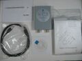
File:Saintsmart dds120 package contents.jpg|<small>Package contents</small> | |||
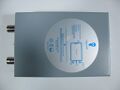
File:Saintsmart dds120 device top.jpg|<small>Device, top</small> | |||
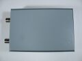
File:Saintsmart dds120 device bottom.jpg|<small>Device, bottom</small> | |||
File:Saintsmart dds120 usb.jpg|<small>USB</small> | |||
File:Saintsmart dds120 connectors.jpg|<small>Connectors</small> | |||
File:Saintsmart dds120 pcb top.jpg|<small>PCB, top</small> | |||
File:Saintsmart dds120 pcb bottom.jpg|<small>PCB, bottom</small> | |||
File:Saintsmart dds120 mxt2088.jpg|<small>MXTronix MXT2088</small> | |||
File:Saintsmart dds120 fx2.jpg|<small>Cypress FX2</small> | |||
File:Saintsmart dds120 microchip 24lc64i.jpg|<small>Microchip 24LC64I</small> | |||
File:Saintsmart dds120 ti cd4052bm.jpg|<small>TI CD4052BM</small> | |||
File:Saintsmart dds120 ams1117-3.3.jpg|<small>AMS1117-3.3</small> | |||
File:Saintsmart dds120 nais 210eh 347.jpg|<small>Unknown IC</small> | |||
</gallery> | |||
== | == Protocol == | ||
We use an open-source firmware for this device (i.e., not the vendor firmware/protocol), hence we do not need to know the vendor protocol. There is some [[SainSmart_DDS120/Info#Vendor_firmware|historic vendor firmware/protocol info]] for those interested, though. | |||
== Firmware == | |||
In order to use this device, the [[fx2lafw|sigrok-firmware-fx2lafw]] (>= 0.1.4) firmware is required. | |||
== | The firmware was originally written by Jochen Hoenicke (see [http://sigrok.org/gitweb/?p=sigrok-firmware-fx2lafw.git;a=blob;f=README README] for details), thanks a lot! | ||
The | '''Note''': The firmware is '''not''' flashed into the device permanently! You only need to make it available in the usual place where [[libsigrok]] looks for firmware files, it will be used automatically (and "uploaded" to the Cypress FX2's SRAM every time you attach the device to a USB port). | ||
See [[SainSmart_DDS120/Info#Open-source_firmware_details|this section]] for technical details about the firmware/hardware. | |||
== Resources == | |||
* [http://www.eevblog.com/forum/testgear/sainsmart-dds120-usb-oscilloscope-(buudai-bm102)/ EEVBlog forum thread] | |||
* [http://www.360customs.de/en/2014/10/usb-oszilloskop-sainsmart-dds120-2-kanal-20mhz-50msps-buudairocktech-bm102/ Detailed description of the hardware] | |||
* [http://www.sainsmart.com/sainsmart-dds-120-20m-50m-s-virtual-oscilloscope-silver.html Vendor product page] | |||
[[Category:Device]] | |||
[[Category:Oscilloscope]] | |||
[[Category:Supported]] | |||
Revision as of 22:08, 8 April 2017
 | |
| Status | supported |
|---|---|
| Source code | hantek-6xxx |
| Channels | 2 |
| Samplerate | 50MHz |
| Analog bandwidth | 20MHz |
| Vertical resolution | 8bit |
| Triggers | none (SW-only) |
| Input impedance | 1MΩ‖25pF |
| Memory | none |
| Display | none |
| Connectivity | USB |
| Website | sainsmart.com |
The SainSmart DDS120 is a USB-based, 2-channel oscilloscope with an analog bandwidth of 20MS/s and 50MS/s sampling rate.
This device appears to be a rebadge of the Rocktech BM102 (or vice versa). The lsusb is exactly the same, the PCB is exactly the same (both have a "656517" and "102LJT1402" silkscreen), and the components used appear to be the same as well.
The device was apparently created by someone named "buudai" in 2012 (also reflected in the lsusb and in the former buudai.com website).
See SainSmart DDS120/Info for more details (such as lsusb -v output) about the device.
Hardware
- USB: Cypress CY7C68013A-100AXC (FX2LP) (datasheet)
- 64-kbyte I²C EEPROM: Microchip 24LC64I (datasheet)
- Crystal: 24MHz
- 145 MHz FastFET Opamps: AD8065ART-R2: (datasheet)
Or in newer hardware:
- Dual 8bit, 100MSPS ADC: MXTronix MXT2088 (datasheet)
- 145 MHz FastFET Opamps: AD8065: (datasheet)
- 4x CMOS differential 4-channel analog mux/demux with logic-level conversion: Texas Instruments CD4052B(M) (datasheet)
Photos
Teardown 1:
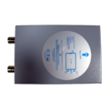
Device, top
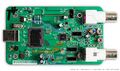
PCB, front
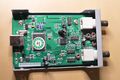
PCB, front
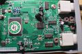
PCB, front
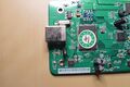
PCB, front
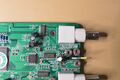
PCB, front
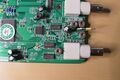
PCB, front
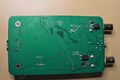
PCB, back
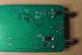
PCB, back
Box
Box
Box


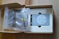
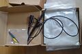
Teardown 2 (purchased 03/2016):
Sticker
Package contents
Device, top
Device, bottom
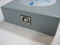
USB
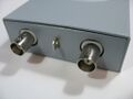
Connectors
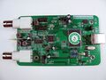
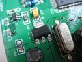
PCB, top
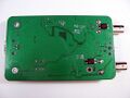
PCB, bottom
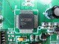
MXTronix MXT2088
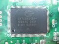
Cypress FX2
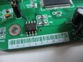
Microchip 24LC64I
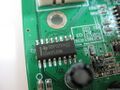
TI CD4052BM
AMS1117-3.3
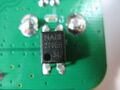
Unknown IC


Protocol
We use an open-source firmware for this device (i.e., not the vendor firmware/protocol), hence we do not need to know the vendor protocol. There is some historic vendor firmware/protocol info for those interested, though.
Firmware
In order to use this device, the sigrok-firmware-fx2lafw (>= 0.1.4) firmware is required.
The firmware was originally written by Jochen Hoenicke (see README for details), thanks a lot!
Note: The firmware is not flashed into the device permanently! You only need to make it available in the usual place where libsigrok looks for firmware files, it will be used automatically (and "uploaded" to the Cypress FX2's SRAM every time you attach the device to a USB port).
See this section for technical details about the firmware/hardware.