Difference between revisions of "MASTECH MS6514"
Jump to navigation
Jump to search
m (Set to "in progress") |
(Added photo gallery) |
||
| Line 23: | Line 23: | ||
== Photos == | == Photos == | ||
<gallery> | |||
File:MASTECH_MS6514_front.png|<small>Device, front</small> | |||
File:MASTECH_MS6514_connectors.jpg|<small>Device, connectors</small> | |||
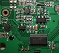
File:MASTECH_MS6514_PCB_front.jpg|<small>PCB, front</small> | |||
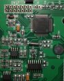
File:MASTECH_MS6514_PCB_back.jpg|<small>PCB, back</small> | |||
File:MASTECH_MS6514_PCB_back_2.jpg|<small>PCB, back, part 2</small> | |||
File:MASTECH_MS6514_PCB_back_3.jpg|<small>PCB, back, part 3</small> | |||
File:MASTECH_MS6514_LCD.jpg|<small>LCD, all segments on</small> | |||
</gallery> | |||
== Protocol == | == Protocol == | ||
Revision as of 21:35, 17 August 2019
 | |
| Status | in progress |
|---|---|
| Source code | mastech_ms6514 |
| Connectivity | USB/serial |
| Measurements | temperature |
| Features | data hold, min/max/avg |
| Website | mastech-group.com |
The MASTECH MS6514 is a logging thermometer with two thermocouple inputs and USB connectivity. It supports K,J,T,E,R,S,N thermocouple types.
The device sends temperature measurements at appr. 2 Hz to the host.
Hardware
- TODO
- SiLabs CP2102 USB interface chip.
Photos
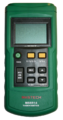
Device, front
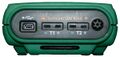
Device, connectors
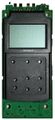
PCB, front
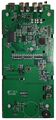
PCB, back
PCB, back, part 2
PCB, back, part 3
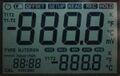
LCD, all segments on


Protocol
The device communicates with the host via a SiLabs CP2102 USB interface chip. Communication parameters are 9600_8_N_1. Live data is transmitted as soon as the button Setup/PC-Link is pressed for 3 seconds.
Commands
| Byte | Description |
|---|---|
| 0xA1 | Start sending stored data |
Received data
| Byte | Bit | Description |
|---|---|---|
| 0 | Always 0x65 | |
| 1 | Always 0x14 | |
| 2 | 0 | 1=READ of stored values, 0=LIVE data |
| 4..3 | Index of stored value (0..999) oldest is 0 | |
| 6..5 | Temperature main display (absolute value without sign) | |
| 8..7 | Temperature aux display (absolute value without sign) | |
| 9 | 5..4 | Mode: 10=SETUP, 11=READ |
| 2..0 | Thermocouple type (1=K, 2=J, 3=T, 4=E, 5=R, 6=S, 7=N) | |
| 10 | 6 | Hold (1=HOLD, 0=not HOLD) |
| 5 | Record active (1=REC, 0=not REC) | |
| 1..0 | Unit (1=°C, 2=°F, 3=K) | |
| 11 | 7 | Sign temperatue main display (1=negative, 0=positive) |
| 6 | Overload temperature main display (1="OL" on LCD) | |
| 3 | Factor temperature main display (1 means divide by 10) | |
| 1..0 | Function main and aux display (00=T1 on main, T2 on aux; 01=T2 on main, T1 on aux; 10=T1-T2 on main, T1 on aux; 11=T1-T2 on main, T2 on aux) | |
| 12 | 7 | Sign temperatue aux display (1=negative, 0=positive) |
| 6 | Overload temperature aux display (1="OL" on LCD) | |
| 3 | Factor temperature aux display (1 means divide by 10) | |
| 1..0 | Function aux display (0=no active, 1=MAX, 2=MIN, 3=AVG). If >0 function defined in byte 11, bit 0-1 is overriden. | |
| 13 | Hours (hh) | |
| 14 | Minutes (mm) | |
| 15 | Seconds (ss) | |
| 16 | Always 0x0D | |
| 17 | Always 0x0A |