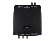
Hantek DDS-3X25
Jump to navigation
Jump to search
The printable version is no longer supported and may have rendering errors. Please update your browser bookmarks and please use the default browser print function instead.
 | |
| Status | planned |
|---|---|
| Frequency (user) | 25MHz |
| Waveforms | user only |
| Waveform memory | 4000 points |
| Amplitude | 0 - 3.5V |
| Connectivity | USB |
| Website | hantek.com |
The Hantek DDS-3X25 is a 25MHz PC-based function generator. It has no external controls, requiring a USB connection to a computer.
See Hantek DDS-3X25/Info for more details (such as lsusb -vvv output) about the device.
Hardware
- FPGA: Xylinx Spartan? 144 pins (20 MHz clock)
- Microcontroller: STM32F103C6(T6A) Mainstream Performance line, ARM Cortex-M3 MCU with 32 Kbytes Flash, 72 MHz CPU, motor control, USB and CAN (8 MHz? clock)
- Output amplifier: LMH6702 1.7 GHz, Ultra Low Distortion, Wideband Op Amp.
- Sync signal output is connected without any buffer or amplifier.
- COUNT IN is connected through TL3016 ULTRA-FAST LOW-POWER PRECISION COMPARATOR.
- Isolated unregulated DC-DC converter MORNSUN A0505S-2W, ±5V, ±200mA
Photos
Protocol
Waveform samples
When sending a waveform to the device, a series of samples denote voltage. These are 12-bit values packed in padded 16-bit integers, sent in network order (most significant part first):
- bits 0-9 are the value, with encoding as shown below
- bit 10
- bit 11 is the sign: 1 for positive, 0 for negative
- bit 12 controls the "sync out" port: 1 is on, 0 is off
- bits 13 is always 1, bits 14-15 are always 0
The value is encoded as 2048 - (voltage * 585). Negative values have all sign and value bits complemented (reversed).
0xA0: configure
Configures the device. The payload is 6 bytes:
| Byte | Bit | Description |
|---|---|---|
| 1 | Mode | |
| 7 | ||
| 6 | ||
| 5 | 1 = Reset external trigger (send only once) | |
| 4 | 1 = External trigger mode enabled | |
| 3 | External trigger: 0 = falling, 1 = rising | |
| 2 | 0 = continuous, 1 = single wave | |
| 1 | Counter reset: 0 = leave, 1 = reset | |
| 0 | Measurement: 0 = frequency, 1 = counter | |
| 2 | ||
| 7 | ||
| 6 | ||
| 5 | ||
| 4 | ||
| 3 | ||
| 2 | ||
| 1 | ||
| 0 | Output: 0 = pattern generator, 1 = programmable output | |
| 3 | Digital I/O pins, bits 0-7 | |
| 4 | Bits 0-3 = digital I/O pins bits 8-11, bits 4-7 unused | |
| 5 | Clock divider, based on 48KHz clock | |
| 6 |
THe response is 10 bytes:
- the first 2 bytes are always 0
- in frequency measurement mode:
- four bytes for the current frequency measurement, in network order. Multiply by 2 to get the actual frequency readout.
- four bytes for a "tick counter" in network order. This has the number of ticks per second, and is used to derive the frequency. Assuming a 100Mhz clock, this counter differs up to 4.17% at 8Mhz from the derived frequency -- investigate.
- in counter mode:
- four bytes for the current counter, in network order.
- four bytes denoting the smoothed out frequency, identical to the first four bytes in frequency measurement mode.
0xA1: point transfer indicator
The payload is 2 bytes:
| Byte | Bit | Description |
|---|---|---|
| 1 | 0-7 | Bits 0-7 of the waveform point count |
| 2 | 0-3 | Bits 8-11 of the waveform point count |
| 4-6 | Unused | |
| 7 | 0=transfer end, 1=transfer start |
There is a 1-byte response: 0xcc
0xA2: unknown
- 6-byte payload: 0000 0000 3000
- 1-byte response: 0xcd
When setting "close output power on", i.e. save configuration to memory:
- no payload
- 1-byte response: 0xcd
0xA3: unknown
- no payload
- 1-byte response: 0x02


