Hantek 4032L
Jump to navigation
Jump to search
 | |
| Status | planned |
|---|---|
| Channels | 32 |
| Samplerate | 400MHz |
| Samplerate (state) | ? |
| Triggers | edge, pattern, pattern duration, combined |
| Min/max voltage | -6V — +60V input, -6V — +6V threshold |
| Memory | 256MiB |
| Compression | - |
| Website | hantek.com |
The Hantek 4032L is an USB-based, 32-channel logic analyzer with up to 400MHz sampling rate and 256MiB memory.
See Hantek_4032L/Info for more details about the device.
Hardware
- Xilinx Spartan-6 XC6SLX16 CSG324 DIV1225 (FPGA, 14579 logic cells, 2 DDR1/2/3 memory controllers, BGA324)
- Cypress FX2LP CY7C68013A-100AXC (USB 2.0 HS controller, TQFP100)
- 2x Micron MT47H64M16HR-25E:H (1Gbit DDR2 SDRAM, BGA)
- TI TPS51116 (DDR memory power controller)
- Unknown I2C EEPROM (marking removed, contains FX2 firmware)
- MXIC MX25L4005 (4Mbit SPI flash, marking removed, contains FPGA bitstream)
Photos
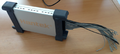
Hantek 4032L with probes
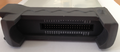
Probe port side
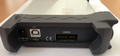
PC USB port side
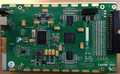
PCB, top
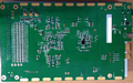
PCB, bottom


Protocol
- Vendor request is used to reset the engine and flush the buffers
- Endpoint 2 is used for host-to-device command/parameters transfers
- Endpoint 6 is used for device-to-host status/data transfers
X denotes "any value" in the following description
Vendor requests
- bRequest=0xB3, wValue=X, wIndex=X, wLength=0x0A, data={ 0x0F, 0x03, 0x03, 0x03, X, X, X, X, X, X } - restart the engine (reset FPGA, reset FIFOs)
- bRequest=0xD0, wValue=X, wIndex=X, wLength=0x00 - disable communication (set FIFO reset), not used
- bRequest=0xD0, wValue=X, wIndex=X, wLength=0x00 - enable communication (clear FIFO reset), not used
Command/Parameters packet
 struct CmdParamsPacket

   byte Magic[2]={ 0x7F, 0x01 }

   byte SampleRate
     0x22 - 400MS/s
     0x23 - 320MS/s
     0x20 - 200MS/s
     0x21 - 160MS/s
     0x00 - 100MS/s
     0x08 - 80MS/s
     0x01 - 50MS/s
     0x09 - 40MS/s
     0x02 - 25MS/s
     0x0A - 20MS/s
     0x03 - 12.5MS/s
     0x0B - 10MS/s
     0x04 - 6.25MS/s
     0x0C - 5MS/s
     0x10 - 4MS/s
     0x05 - 3.125MS/s
     0x0D - 2.5MS/s
     0x11 - 2MS/s
     0x06 - 1.5625MS/s
     0x0E - 1.25MS/s
     0x12 - 1MS/s
     0x07 - 781.25KS/s
     0x0F - 625KS/s
     0x13 - 500KS/s
     0x14 - 250KS/s
     0x15 - 125KS/s
     0x16 - 62.5KS/s
     0x17 - 31.25KS/s
     0x18 - 16KS/s
     0x19 - 8KS/s
     0x1A - 4KS/s
     0x1B - 2KS/s
     0x1C - 1KS/s

   byte TrigFlags
     bit 0 - enable channel A trigger
     bit 1 - enable channel B trigger
     bit 2 - trigger logic, 0 - A or B, 1 - A and B

   word PwmA - channel A Vref PWM value, pseudocode:
     -6V < ThresholdVoltage < +6V
     Vref = 1.8-ThresholdVoltage
     if Vref>10.0
       Vref = 10.0
     if Vref<-5.0
       Vref = -5.0
     pwm = ToInt((Vref + 5.0) / 15.0 * 4096.0)
       if pwm>4095
       pwm = 4095

   word PwmB - channel B Vref PWM value

   byte unused[2]

   dword SampleDepth - sample depth in bits per channel, 2k-64M, must be multiple of 512

   dword PretriggerDepth - pretrigger buffer depth in bits, must be < SampleDepth

   struct Trig TrigA - channel A trigger config, see below

   struct Trig TrigB - channel B trigger config, see below

   byte Command[2] - command, see below
 struct Trig

   TBD
Commands and responses
- { 0x1A, 0x2B } - configure and start capture, all parameters are used
- { 0x3A, 0x4B } - get status, parameters are defaults
- { 0x5A, 0x6B } - get captured data, parameters are defaults
TBD