Difference between revisions of "HSA Logic"
Jump to navigation
Jump to search
Uwe Hermann (talk | contribs) (Set status to Planned.) |
|||
| Line 2: | Line 2: | ||
| image = [[File:Hsa-logic.png|180px]] | | image = [[File:Hsa-logic.png|180px]] | ||
| name = HSA Logic | | name = HSA Logic | ||
| status = | | status = planned | ||
| source_code_dir = hardware/hsa-tple | | source_code_dir = hardware/hsa-tple | ||
| channels = 8 (24 planned) | | channels = 8 (24 planned) | ||
| Line 17: | Line 17: | ||
The '''HSA Logic''' is a USB-based, 8-channel logic analyzer with 6.25 MHz sampling rate. It is an open-hardware / open-source design. Both hardware and software have been developed at [http://www.hs-augsburg.de Hochschule Augsburg] so far. Everything started with [http://hhoegl.informatik.fh-augsburg.de/da/ba-1/USB-TPLE/Documentation/Latex_Thesis/main.pdf this bachelor thesis] in 2010. It was continued in 2013/14 as semester project. | The '''HSA Logic''' is a USB-based, 8-channel logic analyzer with 6.25 MHz sampling rate. It is an open-hardware / open-source design. Both hardware and software have been developed at [http://www.hs-augsburg.de Hochschule Augsburg] so far. Everything started with [http://hhoegl.informatik.fh-augsburg.de/da/ba-1/USB-TPLE/Documentation/Latex_Thesis/main.pdf this bachelor thesis] in 2010. It was continued in 2013/14 as semester project. | ||
== Hardware == | |||
* CPLD: Altera Max II EPM240 with 240 logic elements | * CPLD: Altera Max II EPM240 with 240 logic elements | ||
* microcontroller: Atmel ATmega32u4 (programmed in C) | * microcontroller: Atmel ATmega32u4 (programmed in C) | ||
| Line 25: | Line 25: | ||
== Photos == | == Photos == | ||
<gallery> | <gallery> | ||
File:Hsa-logic front.jpg|<small>PCB, front</small> | File:Hsa-logic front.jpg|<small>PCB, front</small> | ||
| Line 31: | Line 32: | ||
== Firmware == | == Firmware == | ||
CPLD Firmware: written in VHDL, | CPLD Firmware: written in VHDL, | ||
microcontroller Firmware: written in C (using LUFA) | microcontroller Firmware: written in C (using LUFA) | ||
| Line 36: | Line 38: | ||
== Protocol == | == Protocol == | ||
For the sake of simplicity all commands and status messages have been implemented as simple ASCII tokens (single characters). | For the sake of simplicity all commands and status messages have been implemented as simple ASCII tokens (single characters). | ||
=== Commands === | === Commands === | ||
{| class="wikitable" | {| class="wikitable" | ||
|- | |- | ||
| Line 59: | Line 63: | ||
=== Status messages === | === Status messages === | ||
{| class="wikitable" | {| class="wikitable" | ||
|- | |- | ||
| Line 71: | Line 76: | ||
=== Data format === | === Data format === | ||
The samples are blocks of 32 bit: 8 bit data, 16 bit timestamp, 8 bit status. These can be read via the dump command. | The samples are blocks of 32 bit: 8 bit data, 16 bit timestamp, 8 bit status. These can be read via the dump command. | ||
The analyzer only stores new samples if any logic level changes. | The analyzer only stores new samples if any logic level changes. | ||
== Resources == | == Resources == | ||
TODO. | TODO. | ||
[[Category:Device]] | [[Category:Device]] | ||
[[Category:Logic analyzer]] | [[Category:Logic analyzer]] | ||
[[Category: | [[Category:Planned]] | ||
Latest revision as of 20:53, 20 December 2016
 | |
| Status | planned |
|---|---|
| Source code | hardware/hsa-tple |
| Channels | 8 (24 planned) |
| Samplerate | 6.25 MHz |
| Samplerate (state) | ? |
| Triggers | none (SW-only) |
| Min/max voltage | 3.3V; 5.0V |
| Threshold voltage | ? |
| Memory | 1 MB (245K*16), 262144 samples |
| Compression | RLE |
| Website | trac, project page, hhwiki |
The HSA Logic is a USB-based, 8-channel logic analyzer with 6.25 MHz sampling rate. It is an open-hardware / open-source design. Both hardware and software have been developed at Hochschule Augsburg so far. Everything started with this bachelor thesis in 2010. It was continued in 2013/14 as semester project.
Hardware
- CPLD: Altera Max II EPM240 with 240 logic elements
- microcontroller: Atmel ATmega32u4 (programmed in C)
- 2x RAM organised as 256K*16
- I/O drivers supporting 5V and 3V as input voltage
Photos
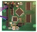
PCB, front
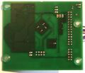
PCB, back


Firmware
CPLD Firmware: written in VHDL, microcontroller Firmware: written in C (using LUFA) TODO.
Protocol
For the sake of simplicity all commands and status messages have been implemented as simple ASCII tokens (single characters).
Commands
| Command | Description |
|---|---|
| 'g' | = go, start sampling |
| 's' | = stop sampling |
| 'r' | = reset |
| 'd' | = dump data (binary) |
| 'D' | = dump data (ASCII encoded) |
| 'i' | = identify |
| 'S' | = get status |
Status messages
| Command | Description |
|---|---|
| 'r' | = measurement is running |
| 's' | = measurement stopped/ no measurement |
| 'f' | = memory is full |
Data format
The samples are blocks of 32 bit: 8 bit data, 16 bit timestamp, 8 bit status. These can be read via the dump command. The analyzer only stores new samples if any logic level changes.
Resources
TODO.