Difference between revisions of "Brymen BM857"
(→Photos) |
|||
| (24 intermediate revisions by 3 users not shown) | |||
| Line 1: | Line 1: | ||
[[File: | {{Infobox multimeter | ||
| image = [[File:Bm_857_mugshot_500000.png|180px]] | |||
| name = Brymen BM857 | |||
| status = supported | |||
| source_code_dir = brymen-dmm | |||
| counts = 50000, 500000(DCV), 999999(Hz) | |||
| categories = CAT III (1000V) / CAT IV (600V) | |||
| connectivity = RS232 | |||
| measurements = voltage, frequency, diode, resistance, continuity, capacitance, current | |||
| features = autorange, data hold, crest, backlight, true-rms, dBmW<sup>1</sup>, %4-20mA | |||
| website = [http://brymen.com/product-html/cata850a/Bm850as.htm brymen.com] | |||
}} | |||
The | The '''Brymen BM857''' is a 50000 counts (500000 DC), CAT III (1000V) / CAT IV (600V) handheld digital multimeter with RS232 connectivity. | ||
<sup>1</sup>: The reference impedance is selectable from 4Ω to 1200Ω. It is not limited to reference impedance of 600Ω. | |||
== Hardware == | == Hardware == | ||
'''Multimeter:''' | '''Multimeter:''' | ||
* TODO | * '''Multimeter IC''': TBD | ||
* '''Precision +2.5V Voltage reference''': [http://www.analog.com/en/special-linear-functions/voltage-references/ref43/products/product.html Analog Devices REF43] | |||
* '''True RMS-to-DC converter''': [http://www.analog.com/en/special-linear-functions/rms-to-dc-converters/ad737/products/product.html Analog Devices AD737] | |||
* '''EEPROM(?)''': Chip marked S24C0. | |||
* '''Unidentified''': Several 062-JRC chips. These appear to be JFET opamps. | |||
* '''Unidentified''': Two QFP64 chips. | |||
* TODO | |||
'''Cable:''' | '''Cable:''' | ||
* TODO | * TODO | ||
See [[User_talk:Mrnuke#BM857_PC_Interface_cable]] | |||
== Photos == | == Photos == | ||
| Line 16: | Line 35: | ||
<gallery> | <gallery> | ||
File:Bm857_box_left.png|<small>Box</small> | |||
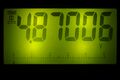
File:Bm_857_mugshot_500000.png|<small>Mughsot | |||
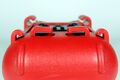
File:Bm857_back.jpg|<small>Device, back</small> | |||
File:Bm857_package_contents.jpg|<small>Package contents</small> | |||
File:Bm857_cable_clips.jpg|<small>Probe cable storage clips</small> | |||
File:Bm857_lcd_backlit.jpg|<small>LCD Backlight</small> | |||
File:Bm857_front_noholster.png|<small>Holster removed, front</small> | |||
File:Bm857_back_noholster.jpg|<small>Holster removed, back</small> | |||
File:Bm857_opened.jpg|<small>Case opened</small> | |||
File:Bm857 inside backside.jpg|<small>Rear cover</small> | |||
File:Bm857_cover_front.jpg|<small>Front cover</small> | |||
File:Bm857_cover_back.jpg|<small>Rear cover, PCB removed</small> | |||
File:Bm857_upperpcb_top.jpg|<small>Upper PCB, top</small> | |||
File:Bm857_upperpcb_bottom.jpg|<small>Upper PCB, bottom</small> | |||
File:Bm857_lowerpcb_top.jpg|<small>Main PCB, top</small> | |||
File:Bm857_lowerpcb_bottom.jpg|<small>Main PCB, bottom</small> | |||
File:Bm857_hv_slots.jpg|<small>High voltage isolation slots.</small> | |||
File:Bm857_hv_walls.jpg|<small>High voltage isolation walls, designed to fit in the isolation slots.</small> | |||
File:Bm857_input_circuit.jpg|<small>Input circuit near the V jack</small> | |||
File:Bm857_mcu+lcdc.jpg|<small>Microcontroller (right), and LCD controller (left)</small> | |||
File:Bm857_mcu+lcdc_2.jpg|<small>Microcontroller (right), and LCD controller (left)</small> | |||
File:Bm857_lcdc.jpg|<small>LCD controller and connector</small> | |||
File:Bm857_ICs.jpg|<small>ICs on the main PCB</small> | |||
File:Bm857_ICs_2.jpg|<small>More ICs</small> | |||
</gallery> | </gallery> | ||
'''Cable:''' | '''Cable:''' | ||
This can use either the BC-85X or the BC-85X-1 cables. See [[Device_cables#Brymen_BC-85X(-1)]]. | |||
Currently, mrnuke is working on an improvised USB-to-infrared converter cable. See [[User_talk:Mrnuke#BM857_PC_interface_cable]] for more details. | |||
<gallery> | |||
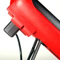
File:Brymen_br85x_dmm_hookup_all.jpg|<small>Cable hookup</small> | |||
File:Brymen_br85x_dmm_hookup_side.jpg|<small>Cable hookup, detail</small> | |||
File:Brymen_br85x_dmm_hookup_angle.jpg|<small>Cable hookup, closeup</small> | |||
File:Brymen_br85x_dmm_hookup_top.jpg|<small>Cable hookup, top detail</small> | |||
</gallery> | |||
== Protocol == | == Protocol == | ||
| Line 33: | Line 84: | ||
[[Category:Device]] | [[Category:Device]] | ||
[[Category:Multimeter]] | [[Category:Multimeter]] | ||
[[Category:Supported]] | |||
Revision as of 18:51, 2 February 2013
 | |
| Status | supported |
|---|---|
| Source code | brymen-dmm |
| Counts | 50000, 500000(DCV), 999999(Hz) |
| IEC 61010-1 | CAT III (1000V) / CAT IV (600V) |
| Connectivity | RS232 |
| Measurements | voltage, frequency, diode, resistance, continuity, capacitance, current |
| Features | autorange, data hold, crest, backlight, true-rms, dBmW1, %4-20mA |
| Website | brymen.com |
The Brymen BM857 is a 50000 counts (500000 DC), CAT III (1000V) / CAT IV (600V) handheld digital multimeter with RS232 connectivity.
1: The reference impedance is selectable from 4Ω to 1200Ω. It is not limited to reference impedance of 600Ω.
Hardware
Multimeter:
- Multimeter IC: TBD
- Precision +2.5V Voltage reference: Analog Devices REF43
- True RMS-to-DC converter: Analog Devices AD737
- EEPROM(?): Chip marked S24C0.
- Unidentified: Several 062-JRC chips. These appear to be JFET opamps.
- Unidentified: Two QFP64 chips.
- TODO
Cable:
- TODO
See User_talk:Mrnuke#BM857_PC_Interface_cable
Photos
Multimeter:
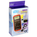
Box
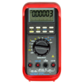
Mughsot
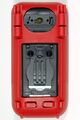
Device, back
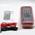
Package contents
Probe cable storage clips
LCD Backlight
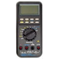
Holster removed, front

Holster removed, back
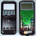
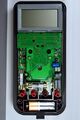
Case opened
Rear cover
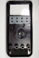
Front cover
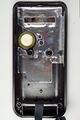
Rear cover, PCB removed
Upper PCB, top
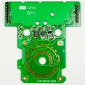
Upper PCB, bottom
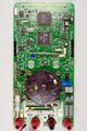
Main PCB, top
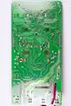
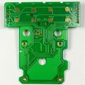
Main PCB, bottom
High voltage isolation slots.
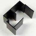
High voltage isolation walls, designed to fit in the isolation slots.
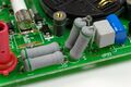
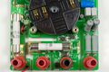
Input circuit near the V jack
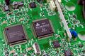
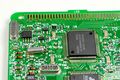
Microcontroller (right), and LCD controller (left)
Microcontroller (right), and LCD controller (left)
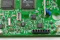
LCD controller and connector
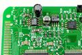
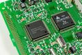
ICs on the main PCB
More ICs


Cable:
This can use either the BC-85X or the BC-85X-1 cables. See Device_cables#Brymen_BC-85X(-1).
Currently, mrnuke is working on an improvised USB-to-infrared converter cable. See User_talk:Mrnuke#BM857_PC_interface_cable for more details.
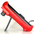
Cable hookup
Cable hookup, detail
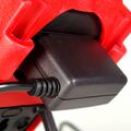
Cable hookup, closeup
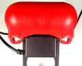
Cable hookup, top detail


Protocol
TODO
Resources
TODO